Camshaft for Alfa Romeo Stelvio OE Equivalent Sourcing
A camshaft for Alfa Romeo Stelvio OE equivalent programs must match the original valve timing geometry, journal dimensions, lobe profile, material hardness, and sensor interface requirements within measurable production limits, not just visual fitment. For distributors and repair-chain buyers, the commercial risk is not limited to whether the part bolts into the engine. A poorly controlled camshaft can create valve train noise, camshaft position correlation faults, accelerated follower wear, low oil-film stability, or repeat labour claims that cost far more than the component itself. Driventus manufactures engine and powertrain components in Taizhou, Zhejiang for aftermarket and contract manufacturing customers in more than 60 countries. For camshaft replacement sourcing, we focus on drawing control, sample approval, metallurgy, machining capability, batch traceability, and release records rather than brand claims. Driventus is an independent aftermarket manufacturer; brand names are referenced for fitment only. This article outlines how procurement teams can evaluate OE-equivalent Stelvio camshafts, what technical and commercial data to request from suppliers, and how Driventus structures quality control for repeatable B2B supply.
What OE-Equivalent Means for Stelvio Camshafts
OE-equivalent does not mean vehicle manufacturer approval. It means the replacement camshaft is engineered to match the functional requirements of the original component for the specified engine application, including valve event timing, bearing interface, oil feed features, phaser or sprocket location, and camshaft position signal geometry. For Alfa Romeo Stelvio replacement programs, buyers should verify more than catalogue fitment.
A sourcing specification should normally include:
- Engine application, engine code where available, production year range, drive side, and market region
- Intake or exhaust camshaft position, because lift profile, trigger geometry, and phaser interface may differ
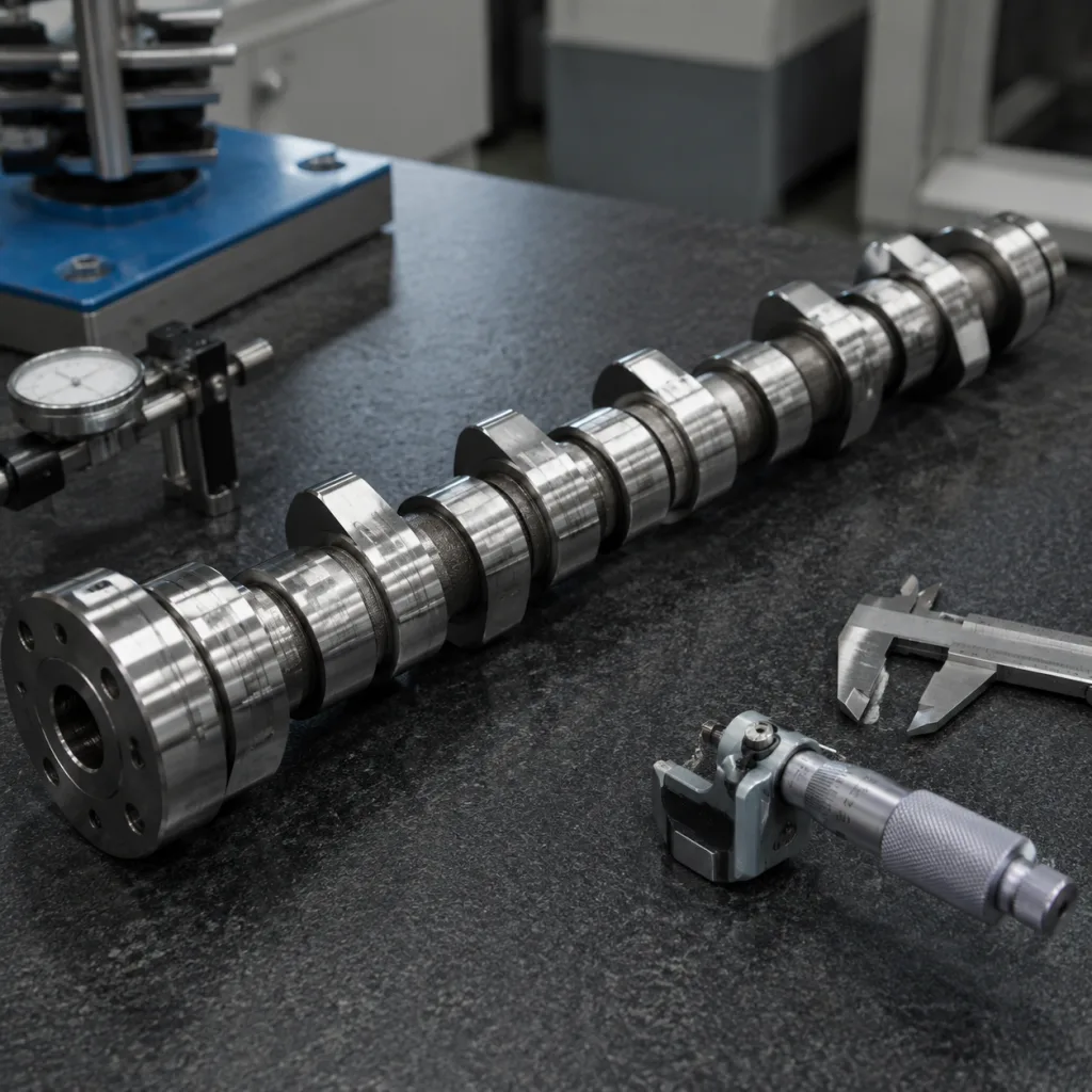
- Overall length, journal diameters, journal width, thrust face dimensions, oil holes, keyway or locating pin, and sprocket or phaser interface geometry
- Cam lobe lift, base circle, opening and closing flank profile, lobe separation reference, and phasing datum against a defined zero point
- Camshaft position sensor trigger geometry where applicable, including tooth width, angular position, air-gap surface, and edge condition
- Material grade, casting or forging route, heat treatment process, surface hardness range, case depth where applicable, and microstructure requirement
- Surface roughness targets for journals and lobes, preservation oil or VCI method, batch code format, carton label rules, and inspection records
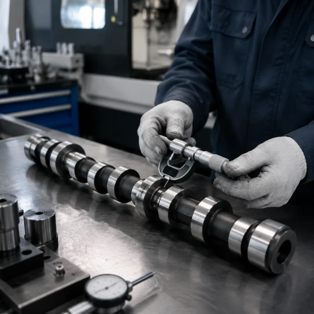
For buyer-controlled drawings, typical measurable targets may include journal diameter tolerance in the 0.010–0.020 mm range, total indicated runout controlled to about 0.03–0.05 mm depending on length, and lobe lift variation held within about ±0.02 mm after grinding. These values must be confirmed against the actual OE sample, drawing, engine family, and customer durability requirement; they should not be treated as universal limits.
Where buyers use internal cross-reference systems, generic OE references may be listed in the format OE 06A… or OE 11251… only when applicable to the existing customer database. Driventus does not claim approval or endorsement by any vehicle manufacturer. Fitment confirmation should be based on samples, drawings, vehicle application data, VIN or engine-code checks where available, and buyer validation.
Dimensional and Material Controls Buyers Should Specify
The camshaft is a timing-critical component. Small deviations in lobe geometry, journal diameter, surface finish, or runout can affect valve event timing, oil film stability, noise performance, and camshaft position correlation. Procurement teams should request measurable limits, inspection frequency, and gauge method instead of relying only on visual samples.
| Control item | Typical verification method | Practical target to define | Procurement relevance | |
|---|---|---|---|---|
| Journal diameter | Micrometer, air gauge, or CMM | Nominal plus 0.010–0.020 mm tolerance band where drawing allows | Oil clearance and bearing durability | |
| Journal roundness/cylindricity | Roundness tester or CMM | Commonly ≤0.005–0.010 mm for precision-ground journals | Stable oil film and low NVH | |
| Total indicated runout | V-block and dial indicator or CMM | Often ≤0.03–0.05 mm depending on length and OE datum | Rotation stability and timing consistency | |
| Lobe lift and base circle | Cam profile measuring equipment | Lift commonly controlled within ±0.02 mm after profile approval | Valve timing and engine output consistency | |
| Lobe angular position | Cam profile machine or CMM fixture | Define against master datum, often within ±0.5° cam angle where required | Valve event phasing and fault-code risk | |
| Surface roughness | Profilometer | Journals and lobes commonly Ra 0.2–0.8 μm depending on design | Wear control and oil retention | |
| Surface hardness | Rockwell, Vickers, or equivalent hardness test | Typical target may be HRC 50–60 or equivalent for hardened surfaces | Wear resistance at lobe and journal surfaces | |
| Case depth, where hardened | Metallographic inspection | Define effective depth and acceptance section, often 1.0–3.0 mm by design | Long-term durability under contact load | |
| Sprocket or phaser interface | Fixture gauge or CMM | Hole, pin, slot, and face position tied to datum scheme | Timing alignment and assembly fit | |
| Sensor trigger geometry | Optical/CMM inspection | Tooth angle, width, edge radius, and face runout defined by sample/drawing | Camshaft correlation signal accuracy |
| Sourcing route | Best fit | Typical MOQ and lead time logic | Advantages | Main controls needed |
|---|---|---|---|---|
| Catalogue replacement | Distributor range expansion and repair-chain supply | Lower MOQ when tooling and semi-finished stock exist; sample dispatch commonly 7–15 days, bulk production often 30–45 days after deposit and approval | Faster quotation, existing tooling, lower development cost | Fitment confirmation, sample inspection, application coverage check |
| Buyer-owned specification | OEM service, Tier-1, or controlled aftermarket program | MOQ normally tied to forging/casting lot, grinding setup, and packaging run; first development can require 60–90+ days | Drawing-based control, defined tolerances, private packaging options | PPAP-style documentation if requested, tooling control, change approval |
| Reverse-engineered sample program | Low-volume or discontinued applications | MOQ is usually higher because profile capture, material analysis, and fixtures must be amortized; timeline depends on sample quality and validation scope | Useful when drawings are unavailable | Multiple OE samples, material analysis, lobe profile capture, buyer validation |