Removing Upper Control Arm: Replacement Buyer's Guide
Removing an upper control arm is rarely just a workshop step. It is the point where the fault, the vehicle variant, and the replacement specification all have to agree. The arm may be coming off because the vehicle has torn bushings, a loose ball joint, collision damage, clunks over bumps, steering pull, or uneven tyre wear. For buyers, the risk is simple: a part that looks close can still move camber, caster, steering return, and tyre wear if the pivot centres, ball-joint taper, bushing clocking, offset, coating, or hardware are wrong. A 1–2 mm error at the pivot or ball-joint centre can be enough to turn a normal alignment into a repeat complaint. This guide treats upper control arm replacement as a sourcing decision, not a generic repair note. It covers when removal should trigger replacement, how to compare complete arms with service parts, which dimensions deserve proof, and what supplier data helps keep fitment repeatable. Driventus is an independent aftermarket manufacturer; brand names are referenced for fitment only.
Decision Point: Why Is the Upper Control Arm Being Removed?
Start with the reason for removal. A control arm removed during a clean chassis rebuild is a different buying case from one removed after tyre scrub, brake dive, or a pothole impact. The fault pattern tells the buyer whether a complete assembly, a bushing kit, a ball joint, or a deeper geometry check is needed.
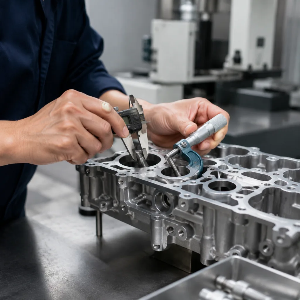
Use the removed part as evidence, not waste. A sound upper control arm should not show cracked rubber, oil-soaked bushings, loose ball-joint preload, distorted mounting eyes, or bends near the ball-joint housing. In the workshop, raise the vehicle by the specified lift points, unload the suspension, check radial and axial ball-joint movement with a dial indicator where possible, and compare left/right arm position before loosening pivot bolts or alignment shims.
Common replacement triggers include:
- Torn or delaminated bushings with visible fore-aft movement under braking or roughly 1–2 mm of sleeve walk.
- Ball joint looseness, torn boot, dry articulation, or stud movement beyond the vehicle maker’s service limit.
- Impact distortion that shifts camber or caster, often visible when the ball-joint centre is compared with the opposite side.
- Corrosion around pivot sleeves, tapered studs, weld toes, or bushing eyes.
- Ovalised bolt holes, torque-loss witness marks, or signs that the sleeve has rotated in the bracket.
If the arm is bent or the ball joint is integrated, replacement is usually safer than pressing in a single part. The same applies where bushing clocking is fixed by design or where removing upper control arm hardware disturbs shims, eccentrics, or alignment references. For procurement, attach the inspection result to the RFQ. It helps the supplier confirm assembly type, side, hardware pack, and any service notes before samples are released.
Fitment Failure Modes That Do Not Show Up in Product Photos
A replacement arm can look right on a screen and still fail at the vehicle. Most fitment problems come from small differences in geometry, hardware, or variant selection. Before ordering, confirm platform, side, model-year break, engine or drivetrain variant, suspension package, ride height, and left-hand/right-hand specificity. For mixed fleets, do not rely on appearance alone. Use VIN, OE number, chassis code, and a removed sample when the application has mid-year changes.
| Failure mode | What causes it | Buyer prevention check | |
|---|---|---|---|
| Alignment cannot be brought into range | Pivot spacing, offset, or ball-joint centre differs | Confirm drawing values or sample match, usually within ±0.5–1.0 mm depending on design | |
| Stud will not seat correctly in the knuckle | Wrong taper, stud length, thread pitch, or nut style | Verify taper angle, usable thread length, nut engagement, and no bottoming in the knuckle | |
| New arm creates noise or harshness | Bushing type, void direction, rubber hardness, or sleeve offset differs | Check bushing orientation, clocking marks, sleeve width, and construction before release | |
| Premature corrosion in service | Coating is thin, incomplete, or unsuitable for road-salt markets | Request coating type, film thickness, and salt-spray or cyclic corrosion target | |
| Hardware loosens or cannot be torqued correctly | Old fasteners reused where new ones are required, or supplied hardware is mismatched | Identify torque-to-yield bolts, prevailing-torque nuts, washers, split pins, and torque notes |
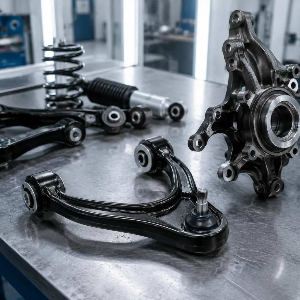
| Option | Advantages | Risks | Best fit |
|---|---|---|---|
| Complete arm | Faster installation, fixed geometry, fewer mixed components | Higher unit price and larger carton volume | Fleet repair, export programmes, high labour cost, downtime-sensitive work |
| Bushing kit only | Lower part cost; useful when the ball joint and arm are sound | Press work, bushing clocking errors, hidden fatigue on aged arms | Controlled workshop rebuilds with correct fixtures |
| Ball joint only | Solves isolated joint wear where the design is serviceable | Poor choice if the arm is bent, corroded, or has aged bushings | Selected applications with replaceable ball-joint design |
| Measurement | Buyer check | Useful specification detail |
|---|---|---|
| Mount-to-mount length | Confirms OE geometry window | Centre distance, bracket width, and offset to ball-joint centre |
| Bushing eye ID/OD | Confirms bolt and sleeve compatibility | Bolt clearance, sleeve length, rubber hardness target, and void orientation |
| Stud taper fit | Confirms seating without forcing or bottoming | Taper angle, small/large diameter, thread pitch, and usable thread length |
| Part mass and section depth | Flags hidden material or process changes | Compare sample mass; investigate deviations above about 5% |
| Finish thickness | Supports corrosion expectations | Zinc, e-coat, powder coat, or paint type with measured film thickness |