oil pressure sensor · 2026-06-16

Low Oil Pressure Oil Pressure Sensor: Diagnosis and Replacement

A low oil pressure warning does not always mean the engine is actually running low on oil pressure. In many cases, the fault sits in the sensor, connector, wiring, or instrument circuit rather than in the lubrication system itself. For procurement teams and workshop buyers, the right first step is to separate electrical failure from a genuine pressure problem before ordering replacements. A low oil pressure oil pressure sensor must match the thread, pressure range, signal type, sealing method, and connector geometry used on the application. Driventus is an independent aftermarket manufacturer; brand names are referenced for fitment only. We supply engine and powertrain components from Taizhou, Zhejiang, to B2B buyers in 60+ countries under IATF 16949:2016 and ISO 9001:2015 controls. If you are cross-referencing OE 06A107065 or another application-specific number, confirm the exact engine code, switch logic, and operating range before purchase.

Decision tree: what a low-pressure warning actually points to

A warning lamp or low-reading gauge can come from several different failure points, and the diagnosis changes the purchasing decision.

  • Actual low oil pressure caused by wear, oil pump problems, a blocked pickup, incorrect oil viscosity, or oil temperature that is too high for the fill.
  • A failed low oil pressure oil pressure sensor with drifted output, a stuck switch point, or an internal diaphragm fault.
  • Connector corrosion, damaged insulation, oil ingress into the plug, or high resistance in the signal wire.
  • A dash warning circuit, ECU input fault, or bad ground reference.

The symptom does not prove sensor failure. If the engine has been run with the lamp on, treat it as a lubrication risk first and inspect mechanically before fitting a new part. As a practical benchmark, many passenger-car systems use warning switches around 0.3-0.8 bar at low-speed idle, while transducer-style senders often operate in ranges such as 0-5 bar, 0-10 bar, or 0-12 bar; the exact threshold must match the platform spec.

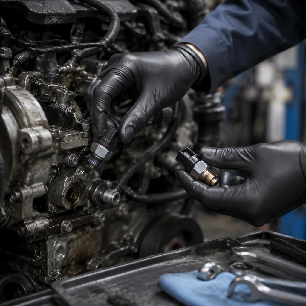
Step-by-step: verify the fault before you order

Use a simple symptom-to-cause sequence instead of replacing parts by appearance.

1. Check oil level, oil grade, filter condition, and service history; confirm the oil meets the viscosity grade required by the engine family. 2. Confirm when the warning appears: at cold start, idle, hot idle, under load, or on hot restart after soak. 3. Measure mechanical oil pressure with a calibrated gauge at the sender port; use the correct adapter and bleed air from the test line. 4. Compare the reading with the vehicle specification at idle and at higher rpm, typically checked at 700-900 rpm idle and around 2,000-3,000 rpm for a quick shop check. 5. Inspect the connector for oil contamination, bent terminals, fretting, broken locks, or water ingress; check harness pull relief and rub-through points. 6. Check continuity, resistance to ground, and reference voltage if the unit is a transducer rather than a simple switch. 7. If the vehicle uses a warning switch, verify the opening/closing point with a pressure pump on the bench before ordering the replacement.

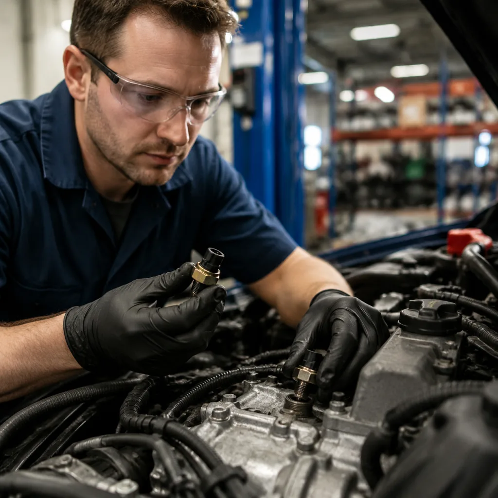
What to verify on the bench

  • Thread form and sealing method: M10x1, M12x1.5, 1/8"-27 NPT, BSPT, parallel thread with sealing washer, or taper thread sealant application.
  • Electrical interface: single-pin switch, two-pin sensor, three-pin transducer, or variable-resistance output.
  • Pressure set point or operating range; many aftermarket buyers specify tolerance at ±0.1-0.2 bar for switch logic and ±2-5% FS for analog sensors, depending on the programme.
  • Housing length, hex size, and terminal orientation for harness clearance and wrench access.
  • Temperature exposure around the mounting point; oil gallery locations can see 120-150°C in normal service and higher during overheating.
  • Torque requirement for installation; common light-vehicle sender threads may tighten in the 15-30 N·m range, but the application spec should always be followed.

These checks reduce comebacks and prevent ordering a visually similar part that fails in service.

Failure modes: how symptoms map to root cause

The table below shows the most common failure patterns and what they usually indicate.

</tr></thead><tbody> </tbody></table>If the sensor is part of a broader lubrication complaint, validate the replacement against the same pressure curve or switch threshold used by the vehicle platform. For fleet buyers, record the measured pressure at idle and 2,500 rpm on the job card so the root cause can be traced on repeat visits.

Failure modes: how symptoms map to root cause

Comparison: buying by fitment data, not catalogue lookalikes

For B2B sourcing, purchasing decisions should be based on measurable fitment data rather than visual similarity.

  • Thread specification and sealing type, including pitch and whether a crush washer, sealant, or taper seat is required.
  • Operating pressure range or switching threshold, plus the acceptable tolerance band.
  • Electrical pin count, terminal geometry, and connector keying.
  • Housing material, plating, and corrosion resistance for road-salt or high-humidity service.
  • Temperature range, vibration resistance, and ingress protection expected by the programme.
  • Pack-level traceability, lot coding, and date code format.
  • PPAP, dimensional report, or sample approval requirements for controlled accounts.

Driventus manufactures under IATF 16949:2016 and ISO 9001:2015 quality controls, with material and process discipline suitable for export markets. Where customer programmes require additional compliance alignment, we can support documentation against relevant requirements such as REACH (EC) No 1907/2006. For buyers comparing part families, our catalog can be used to narrow the fitment, and our quality system page explains the controls behind incoming inspection, process checks, and final release. If your programme needs a private-label or dimensional match approach, our custom manufacturing service is available for approved volumes.

For quotation work, a useful buyer brief includes annual demand, target pack size, sample photos, OEM or OE cross-reference, expected annual usage by SKU, and whether the part will be sold loose, boxed, or in kit form. As a sourcing rule of thumb, prototype or validation orders often carry a higher unit price than production volumes; MOQ may be 50-200 pieces for sample tooling runs, 500-1,000 pieces for stable export packaging, and 2,000+ pieces for programme pricing, depending on complexity and packaging. Typical lead time can be 7-15 days for in-stock or simple repeat items, 25-35 days for standard production, and 45-60 days for new tooling, color changes, or custom labeling, subject to capacity and raw material availability.

When to replace versus rebuild the diagnosis

Replace the sensor when all of the following are true:

  • Mechanical oil pressure is within specification at the sender port and under the relevant temperature condition.
  • Wiring, terminals, grounds, and connector seals pass inspection and continuity checks.
  • The warning or gauge fault follows the sender, not the harness or instrument cluster.
  • The application match is confirmed by thread, range, connector geometry, and sealing method.

Do not replace the sensor first if there is evidence of bearing noise, oil starvation, sludge, blocked pickup, pump wear, or oil aeration. In those cases, the sender may only be reporting a real engine problem. A practical workshop threshold is simple: if hot idle pressure is below spec by more than about 10-15%, or if the pressure falls sharply as rpm rises, investigate the lubrication system before installing a new sender.

For repair chains and distributors, the lowest return rate comes from pairing correct diagnosis with verified replacement parts, not from stocking a single universal item. Build the approval process around measured pressure, photos of the installed connector, and a confirmed OE or engine-code cross-reference before issuing a purchase order.

When to replace versus rebuild the diagnosis

Supply scenarios: aftermarket, OEM, and urgent service

Driventus supplies oil pressure sensors and related engine components to aftermarket distributors, wholesalers, OEM and Tier-1 programmes, and multi-location repair chains. Buyers can source from our catalog, review process control details in our quality system, and discuss target drawings or labelling requirements through custom manufacturing.

Driventus is an independent aftermarket manufacturer; brand names are referenced for fitment only.

For a procurement review, the key commercial inputs are application list, annual volume, required packaging, target lead time, target price band, and validation scope. If the part must match an OE 06A107065 cross-reference or another application-specific code, send the engine code, connector photo, sample dimensions, and desired annual consumption with your enquiry. That shortens approval time and reduces the risk of wrong-fit shipments.

As a sourcing starting point, buyers often evaluate landed cost by comparing unit price, packaging cost, freight mode, customs duty, and expected return rate. A simple buying rule works well: lower MOQ can suit service parts and catalogue expansion, while higher forecast volumes justify tooling review, custom logo printing, and tighter tolerance control on terminal depth, thread engagement, and switch point. For urgent service campaigns, ask whether partial shipments, mixed-SKU cartons, or air-freight release are available so the purchase order can be split without delaying first deliveries.

Frequently asked questions

Measure oil pressure with a mechanical gauge first, using the sender port and the correct adapter. If pressure is within spec and the warning remains, inspect the sender, wiring, and connector. Replace the sensor only after the mechanical reading is confirmed and the set point or output curve matches the vehicle spec.

Only if the thread, sealing method, pressure range, terminal layout, and connector keying all match. Similar-looking parts often differ in set point, harness angle, or thread depth, which can cause false warnings or no signal. Buyers should verify engine code, OE cross-reference, and measured dimensions before ordering.

Ask for dimensional data, electrical specifications, traceability details, and quality certifications such as IATF 16949:2016 and ISO 9001:2015. If needed, request compliance support for REACH (EC) No 1907/2006, plus sample photos, carton markings, and lot code format for receiving inspection.

If you need a verified replacement or a programme-specific cross-reference, send your target application and sample details through /contact.html.

Request a Quote
Symptom Likely cause Inspection point Action
Lamp stays on with engine runningSensor stuck closed, wiring short, or true low pressureMechanical gauge, connector, harnessReplace only after pressure check
Lamp flickers at idle when hotWorn engine, low-viscosity oil, weak pump, clogged pickup, or unstable sensorHot idle pressure, oil spec, oil temperatureConfirm engine condition first
Gauge reads zero intermittentlyOpen circuit, connector corrosion, failed sender, or terminal spreadTerminal tension, continuity, wiggle testReplace sender if wiring is sound
Reading is high or erraticSensor drift, poor ground, signal interference, or wrong part numberOutput test, ground path, part cross-checkReplace and retest
Warning appears only after repair workPinched harness, damaged connector lock, incorrect sealing, or wrong thread engagementVisual inspection, torque check, thread matchRework installation and verify