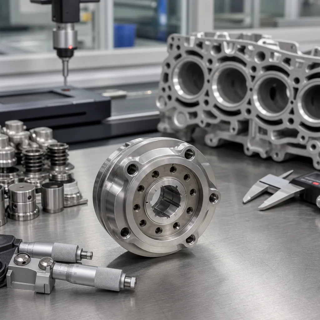
Fuel injector dimensions are more than one number on a catalogue page. For procurement, engineering, and quality teams, the useful data set includes the full package envelope, rail and manifold/head interface diameters, O-ring gland geometry, seal-land locations, tip protrusion, mounting and retainer features, connector keying, and the tolerance stack that determines installed fit. The same nominal injector may suit one engine family and fail in another if a seal land, electrical key, nozzle stand-off, clip groove, or rail-seat datum moves by only 0.1–0.3 mm. This guide highlights the dimensional details buyers should request before sampling, PPAP review, or purchase order release. Driventus is an independent aftermarket manufacturer; brand names and OE references are used for fitment identification only. For controlled production, dimensional records should be managed through an IATF 16949:2016 control plan, with material declarations aligned to ISO 9001:2015 and REACH (EC) No 1907/2006 where applicable.
What injector dimensions actually cover
When buyers ask for fuel injector dimensions, they are usually asking about the complete interface package, not just the body length shown in a catalogue. The injector has to locate correctly in the fuel rail, seal at the upper and lower interfaces, connect to the harness without modification, and place the nozzle at the intended stand-off from the intake port or combustion chamber. A visual match helps with first screening, but it is not enough for release.
The main dimensional items include the outside envelope, upper and lower seal diameters, O-ring groove width and depth, connector cavity and latch form, terminal pitch, distance from the rail seating datum to the nozzle tip, location of any clip or retainer groove, filter-basket interface, and nozzle-cap or pintle-end geometry. On some applications, connector clocking is just as important. The angular position of the electrical connector relative to the spray outlet or retainer groove can decide whether the harness, rail bracket, intake runner, or engine cover clears the part.
A good drawing separates functional characteristics from cosmetic features. A 0.2 mm shift in a non-sealing mould witness line is usually harmless. The same 0.2 mm shift in O-ring gland depth, retainer groove position, terminal location, or installed tip height can create fuel leakage, excessive insertion force, poor spray targeting, connector mislock, or rail misalignment. The datum scheme matters as well. Dimensions should reference controlled features such as the rail seat, lower seal seat, machined shoulder, or nozzle-end datum, rather than flexible caps or uncontrolled plastic edges that vary with moulding and assembly conditions.
For procurement, the practical question is simple: will the part fit the complete fuel-system hardware without rework? Interchangeability checks should therefore cover the injector, fuel rail bore, harness plug, intake manifold or cylinder-head bore, retaining clip, service seal kit, and packaging caps. If a supplier can provide only a photo and an overall length, the dimensional data set is incomplete for B2B sourcing.
Reference dimensions to check first
Initial screening should focus on the dimensions that affect fit, sealing, electrical connection, axial retention, and installed nozzle position. A practical control sheet usually starts with the OE drawing, customer print, or a measured retained sample, then compares every critical interface against the proposed replacement. For B2B sourcing, the goal is not to collect every possible measurement. It is to confirm the dimensions that could stop assembly, cause leakage, alter fuel delivery, or change emissions-critical spray placement.
Dimension
Typical control point
Why it matters
Typical control band
Overall length
Tip datum to connector end or upper body end
Clearance to rail, manifold, cover, and harness route
±0.10 mm to ±0.30 mm
Installed height
Rail-seat datum to lower seal or nozzle datum
Controls rail compression, axial seating, and injector depth
±0.05 mm to ±0.10 mm
Main body diameter
Cylindrical metal or moulded section
Bore fit, clamp stability, vibration control, and rail clearance
±0.03 mm to ±0.08 mm
Upper O-ring size
Rail-side seal OD, ID, and cross-section
Fuel leakage at rail interface and insertion force
±0.02 mm to ±0.05 mm
Lower O-ring size
Manifold or head-side seal OD, ID, and cross-section
Air leakage, fuel vapour leakage, and service-fit repeatability
±0.02 mm to ±0.05 mm
O-ring groove width/depth
Upper and lower gland features
Seal squeeze, retention, extrusion gap, and swelling allowance
±0.03 mm to ±0.06 mm
Tip protrusion
Seat datum to nozzle end
Spray targeting, wall wetting, combustion stability, and deposit risk
±0.05 mm to ±0.10 mm
Connector keying
Cavity form, latch, terminal pitch, terminal size, and orientation
Harness compatibility, polarity control, and CPA/secondary lock fit
100% visual plus go/no-go or mating-plug check
Retainer groove location
Clip seat position from rail datum
Positive locking in the rail and axial retention under pressure and vibration
±0.05 mm to ±0.10 mm
Nozzle seat length
Lower seal face to tip datum
Installed depth and nozzle stand-off
±0.05 mm to ±0.10 mm
Spray-hole orifice location
Nozzle-end feature position and clocking
Alignment with port, chamber, or tumble/swirl strategy
Drawing-defined
</tr></thead><tbody> </tbody></table>These bands are typical working ranges for controlled production parts, not universal acceptance limits. The approved drawing, customer specification, application test plan, and validation results always take priority over generic ranges. Port fuel injection and gasoline direct injection also call for different levels of scrutiny. Typical port systems operate around 3–5 bar, while gasoline direct injection systems may operate from roughly 50 bar to more than 300 bar, depending on generation and application. Direct-injection parts therefore require tighter control of seat geometry, body strength, nozzle tip location, sealing faces, and cleanliness.
A useful sourcing rule is to treat any dimension affecting sealing, alignment, electrical locking, retention, or installed depth as a critical-to-quality characteristic. Those items should be measured on first articles, linked to a drawing revision, and checked again after tool repair, cavity change, material change, machining-datum change, seal-compound change, or process relocation.
Tolerances, materials, and fuel compatibility
Dimensions cannot be separated from material selection or operating environment. Stainless or plated steel bodies, stainless internals, engineered polymers for connector housings, and elastomer seals such as FKM or HNBR all influence the final envelope, insertion force, compression set, and long-term dimensional stability. A part can pass incoming inspection and still fail later if the seal compound swells in E85, diesel additives attack an elastomer, or a plastic connector relaxes after under-hood heat ageing.
What to specify with the drawing
Fuel type and blend: petrol/gasoline, E10, E20, E85, diesel, biodiesel blend such as B7 or B20, methanol blend where relevant, or regional blended fuel
System pressure: port-injection and direct-injection programs need different body, seat, leakage, and burst-pressure controls
Seal compound: FKM, HNBR, FVMQ, or another approved material, with fuel and temperature compatibility stated
Seal hardness and compression target: commonly specified in Shore A, with squeeze and gland fill checked against rail and manifold bore conditions
Plating or coating: corrosion resistance, wear protection, salt-spray requirement, coating thickness, and electrical grounding where applicable
Thermal exposure: cold-start temperature, under-cover heat soak, tip temperature, and thermal cycling profile
Cleanliness requirement: particle-size and particle-count limits to protect the seat, filter basket, and spray holes
Tolerance stack-up should be reviewed as an assembly condition, not as a set of isolated print dimensions. Upper seal compression, retainer groove location, rail bracket position, lower bore depth, manifold machining tolerance, and clip thickness all combine to determine whether the injector seats without side load. Even when each individual feature is inside tolerance, a stack biased toward the same limit can make the assembled rail difficult to install or load the injector at an angle.
A dimensional match does not guarantee a functional flow match. Two injectors can share the same outer profile but differ in static flow rate, dynamic flow at short pulse widths, latency/dead time, spray angle, droplet distribution, atomisation quality, internal volume, or coil characteristics. For sourcing release, the dimensional report should be packaged with flow-rate data at the specified pressure, leak-test results, spray-pattern verification, coil resistance, response-time data where required, and durability or endurance evidence.
For regulated programs, material disclosure should support REACH (EC) No 1907/2006, while the supplier quality file should sit within ISO 9001:2015 and IATF 16949:2016 controls. For repeat orders, revision discipline is essential. Seal compound, plating thickness, mould tooling, machining datum, filter basket, nozzle cap, coil winding, and test method changes should be approved before shipment, not discovered after field installation.
How we verify dimensional stability
Dimensional control starts with the approved drawing and ends with inspection records that can be traced to a production lot. On an injector sourcing program, the core checks normally include CMM measurement for datum relationships and axial distances, optical or vision inspection for connector and tip geometry, go/no-go gauges for seal lands and plug fit, pin gauges or profile checks for critical bores, and pressure/leak testing after assembly.
A practical validation sequence is:
1. Review the OE reference, customer drawing, or retained sample against the intended engine family, rail style, manifold/head bore, and harness connector. 2. Define datums, critical dimensions, special characteristics, gauges, sample size, and acceptance criteria before first-article inspection. 3. Measure critical dimensions on first articles and compare them with the signed-off print and tolerance stack. 4. Confirm insertion force, clip retention, rotational clearance, connector engagement, and sealing at installed depth. 5. Run static flow, dynamic flow where required, spray pattern, coil resistance, response, insulation, and leak tests on the same sample lot. 6. Check heat-ageing, thermal cycling, or fuel-soak samples where seal swelling, connector stability, coating durability, or dimensional drift is a risk. 7. Lock the result into a control plan, incoming inspection routine, gauge plan, and lot traceability record.
Measurement method matters because small injector features are easy to distort or misread. Soft seals should not be compressed during dimensional measurement unless the method defines a controlled compression load. O-ring cross-section should be measured with appropriate non-damaging equipment, not with high jaw force that flattens the seal. Connector keying should be confirmed with the mating plug or a qualified gauge, not only by measuring one plastic rib. Tip protrusion and installed height should be measured from repeatable datums so that supplier, buyer, and assembly-plant results correlate.
For critical dimensions, many buyers expect process capability of at least Cpk 1.33 once the process is stable; higher-risk or high-volume characteristics may be controlled to Cpk 1.67 depending on the customer requirement. This is not a universal legal rule, but it is a defensible sourcing threshold when the part has a narrow fit window. Where volume is high or the rail design has little tolerance margin, capability studies, MSA or gauge R&R, calibrated gauges, and periodic layout inspection provide better protection than a one-time sample report.
If a supplier cannot show repeatable measurement records, signed inspection standards, gauge-control evidence, and lot-level traceability, the risk is usually greater than the unit-price saving. Dimensional stability is not only a metrology topic; it is what keeps replacement injectors installable across multiple production batches.
Sourcing checks before you release an order
Before placing an order, send a complete RFQ pack. Include the OE reference where available, part markings, a retained sample or calibrated photo set, engine code, vehicle application, fuel type, rail style, connector photo, annual volume, target market, required certifications, and any measured dimensions from the removed part. Photos should show the connector face, latch, terminals, upper seal area, lower seal area, nozzle end, retainer groove, body clocking, and full side profile beside a scale or caliper.
For buyers comparing supply options, use these internal checkpoints:
Can the part be matched to a controlled drawing rather than only a catalogue image?
Are the upper and lower seal diameters, cross-sections, groove dimensions, and tip protrusion confirmed?
Is the connector keying checked against the mating harness plug, terminal gauge, or qualified go/no-go gauge?
Is the retainer groove location verified from the correct rail-seat datum?
Is the test data tied to the same revision level as the drawing, sample lot, tooling status, and seal compound?
Are static flow, dynamic response where required, spray pattern, leak rate, coil resistance, and insulation checks included with the dimensional report?
Does the supplier identify seal material, coating, fuel compatibility, pressure range, temperature range, and cleanliness requirement?
Does the supplier provide traceability by lot, shift, tool/cavity, operator or line, incoming material batch, and inspection record?
Are packaging, nozzle-cap protection, rail-end caps, cleanliness, corrosion protection, and service seal requirements defined for shipment?
A strong RFQ also asks the supplier to state what is interchangeable and what is not. For example, an injector may share the same upper rail connection but use a different nozzle cap, spray angle, connector latch, terminal style, or lower seal package. Those differences can be acceptable in one aftermarket program and unacceptable in another, depending on engine calibration, emissions requirements, installation constraints, and service expectations.
Driventus supports aftermarket and OEM/Tier-1 supply programs from Taizhou, Zhejiang, with dimensional control, incoming material checks, application review, and documented release records. If you are replacing an existing part, request a direct-fit review rather than relying on a visual match. For injected fuel systems, the tolerance stack is usually more important than the photograph, and the best sourcing decisions are made before the first shipment leaves the factory.
Frequently asked questions
Start with overall length, installed height, body diameter, upper and lower O-ring sizes, O-ring groove dimensions, connector keying, retainer groove location, and tip protrusion. These features control fit, sealing, electrical compatibility, axial retention, and nozzle position. Flow rate is also essential, but it does not replace dimensional verification.
Yes. The external envelope can match while seal lands, internal seat depth, connector pitch, terminal style, coil resistance, spray angle, flow rate, or nozzle stand-off differs. That is why a drawing review, mating-plug check, installed-fit check, and flow/spray validation are needed before release.
Send the OE reference, part markings, engine code, fuel type, photos of both ends, measured dimensions, annual volume, and target market. If possible, include the old injector, harness plug photo, rail bore diameter, lower bore diameter, connector details, and a physical sample so the supplier can confirm fit faster.
Send the OE reference, sample photos, measured fuel injector dimensions, and target volume, and we will confirm dimensional feasibility, validation scope, and supply options in [request a quote](/contact.html).