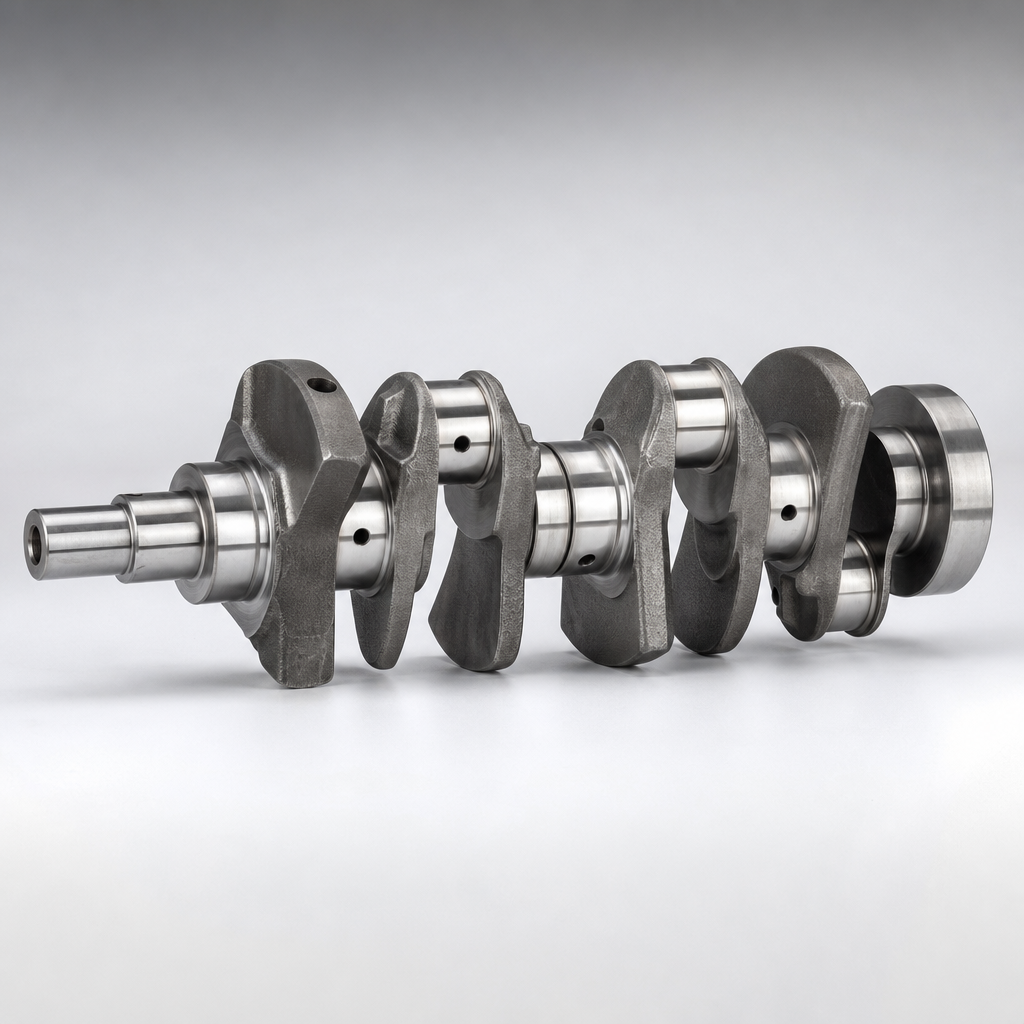
A front crankshaft oil seal leak is often blamed on the seal alone, but the seal is only one part of a larger system. For buyers, distributors, workshop groups, and warranty teams, the real task is to separate the visible oil leak from the underlying cause. Common root causes include crankshaft surface wear, housing distortion, excessive crankcase pressure, installation damage, pulley runout, and use of the wrong seal material for the application.
That distinction matters. Replacing the seal without correcting the actual fault may stop the leak briefly, then send the engine straight into another failure cycle. In repeat-return cases, the problem is often not a defective seal by itself, but a mismatch between seal design, shaft condition, and operating environment.
This article explains front crank seal leak causes and fixes in a practical way for B2B readers: how to confirm the leak source, how to sort the likely failure mode, what to measure before approving a replacement, and what sourcing details actually reduce repeat claims. Driventus is an independent aftermarket manufacturer; any brand names or OE references are mentioned for fitment and cross-reference purposes only.
From a sourcing and service-control perspective, the useful question is not just why is oil leaking now. It is what measurable condition must be checked before another seal goes in. Buyers should expect specification detail such as shaft diameter range, seal material, lip type, runout limit, housing tolerance, installation depth, packaging protection, and supplier batch traceability. Without those controls, a low unit price can quickly turn into repeat labour, warranty returns, and stock write-offs that cost far more than the seal itself.
Start here: confirm it is really the front crank seal
The front crankshaft seal sits where the crankshaft exits the timing cover or front cover. Its job is simple: keep oil in while the shaft rotates through heat, speed, and vibration. In the field, however, the leak pattern is rarely simple.
Typical signs include:
Oil residue around the crank pulley or harmonic damper
Oil mist or spray inside the lower timing cover area
Auxiliary belt contamination
Squeal or slip from oil-contaminated belts
Burnt oil smell after operation
Gradual oil level loss without an obvious sump or rocker cover leak
Premature deterioration of rubber belts exposed to oil
Dirt accumulation sticking to an oily area around the front cover
The catch is that the wettest area is not always the source. Oil moves with rotation and airflow. A front cover gasket, camshaft seal, oil pump seal, valve cover leak running downward, or sump corner joint can all imitate a front crankshaft seal problem. On some engines, oil travels along the crank pulley and is thrown outward, making the leak look larger or farther away from its origin.
Before authorising replacement, clean the area thoroughly, run the engine, and trace the first fresh oil path. UV dye, talc, or borescope inspection helps where access is poor. This step is basic, but it prevents unnecessary seal swaps and improves warranty accuracy.
A practical 10 to 15 minute confirmation routine looks like this:
1. Degrease the front cover, pulley, and surrounding area. 2. Idle the engine for 5 to 10 minutes, then briefly raise speed to 2,000 to 3,000 rpm if safe. 3. Re-check for the first fresh oil point. 4. If the source is still unclear, add UV dye and reinspect after a short road test or dyno run.
A true front seal leak often shows as a circular wet pattern behind the pulley hub or as oil emerging concentrically from the shaft centerline. A valve cover leak usually tracks downward from above. A front cover gasket leak more often follows a vertical or diagonal path along the casting split line.
For buyers managing broad engine-component ranges, this is also why related sealing and rotating-engine items are often reviewed together in our catalog and, where relevant, under /products/engine-components.html.
Failure mode map: what usually causes the leak and how to tell them apart
A front crank seal leak generally falls into five root-cause groups. More than one can exist on the same engine, which is why fast diagnosis matters.
Symptom or finding
Probable cause
What to inspect
Typical fix
Oil tracks from seal lip soon after replacement
Installation damage or wrong seal orientation
Lip condition, garter spring retention, insertion depth, installation marks
Replace seal and install with correct driver and procedure
Cold-start seepage, hardening, shrinkage, or rapid ageing
Elastomer incompatibility or thermal ageing
Seal material specification, service temperature history, oil chemistry
Use the correct NBR, FKM, or PTFE design
</tr></thead><tbody> </tbody></table>## 1. Shaft damage: the common repeat-failure driver
The sealing lip runs directly on the crankshaft surface. If that surface has a groove, corrosion pitting, chatter marks, burrs, or excessive runout, a new seal may fail quickly even if the seal itself is dimensionally correct.
A polished wear groove is one of the most common reasons a front crank seal leaks again after replacement. The new lip simply follows the old track.
As a practical reference, many rotary oil seal applications expect shaft roughness around Ra 0.2 to 0.8 μm with no directional machining marks that pump oil outward. Shaft hardness, depending on design, is often targeted at 45 HRC minimum or a hardened running surface or sleeve. A groove depth above roughly 0.05 to 0.10 mm commonly justifies a repair sleeve or a repositioned lip track, depending on the application.
Typical shaft runout control for reliable lip sealing is often in the range of 0.05 to 0.15 mm TIR at the sealing surface. If wobble exceeds that, the issue may be the pulley, damper, crank snout, or front main bearing condition rather than the seal.
2. Crankcase pressure: often missed, often expensive
A blocked or restricted positive crankcase ventilation system can force oil past an otherwise serviceable seal. If oil is also visible at rocker cover gaskets, cam seals, dipstick tube interfaces, or other weak sealing points, overpressure should be checked before another seal is approved.
High crankcase pressure may result from a blocked PCV valve, restricted breather hose, sludge in ventilation passages, or excessive blow-by on a worn engine. Unless that pressure source is corrected, even a high-quality replacement seal can be overwhelmed.
In workshop diagnosis, crankcase pressure is often checked with a manometer or low-pressure gauge at idle and at elevated rpm. Exact limits depend on engine design, but persistent positive pressure where the engine should show slight vacuum or near-neutral pressure is a warning sign. On repeat leak cases, recording the reading before and after PCV correction is useful evidence for warranty review.
3. Installation error: still a major field issue
Front crank seals are easy to damage during fitting. Common mistakes include cocking the seal in the bore, over-driving it, nicking the lip on a keyway or shaft edge, contaminating the lip, or using the wrong pre-lubrication method. Some PTFE seals are installed dry and require a stabilisation period before engine start, while many elastomer lip seals require lubrication at the lip during installation.
Common process errors include:
Driving the seal on one side first and creating angular misalignment greater than 0.2 to 0.3 mm across the face
Failing to use a lead-in sleeve over keyways, threads, or sharp shaft shoulders
Installing to the wrong depth so the lip runs on an existing wear groove
Starting the engine immediately after fitting a dry-install PTFE seal when a supplier requires a dwell period, often 2 to 4 hours
Applying RTV or anaerobic compound to an OD design that was intended to rely only on press fit or a pre-applied coating
For B2B buyers, these are not small workshop details. They drive claim rate, so seal sourcing should be tied to installation guidance, packaging, and training support, not just part number matching.
Pre-replacement gate: the inspection checklist that prevents repeat jobs
For workshop networks, distributors, and warranty teams, a standard inspection routine is one of the simplest ways to reduce repeat labour claims. The goal is to decide whether the seal is the cause, part of the cause, or just the most visible symptom.
Check these points before replacing anything
Leak source confirmation: clean the area, run the engine, and trace the fresh oil path
Crankshaft snout condition: check for grooves, scoring, corrosion, burrs, or a polished wear track
Shaft runout: measure if vibration, pulley wobble, or damper damage is suspected
Seal bore and front cover: inspect for nicks, scratches, fretting, out-of-round condition, or distortion
Pulley and damper fit: verify correct seating, no wobble, and no abnormal misalignment
Keyway and shaft lead-in condition: ensure there are no sharp edges that could cut the seal lip during installation
Crankcase ventilation: inspect the PCV valve, breather hoses, separators, and internal passages for restriction
Installation evidence: confirm the previous seal was not tilted, over-driven, reversed, or installed with the wrong lubrication method
Material match: verify whether the replacement used NBR, FKM, or PTFE as required by service temperature, oil chemistry, and engine design
Operating history: note overheating events, long drain intervals, contamination, or prior front-end repairs that may affect sealing performance
Measurement points that matter in repeat-failure cases
Shaft diameter at seal track: measure at 3 axial positions and 2 directions, 90° apart. Compare against drawing or catalog nominal size and check for taper or ovality. As a practical screening rule, ovality above 0.03 to 0.05 mm is usually cause for concern.
Shaft surface finish: confirm no spiral machining marks. A typical acceptance range is Ra 0.2 to 0.8 μm.
Runout at sealing track: check with dial indicator. Many applications aim for ≤0.10 mm TIR, while anything beyond 0.15 mm increases risk of pumping and lip instability.
Housing bore size and roundness: verify with bore gauge where claims are repeated. OD press-fit seals commonly rely on bore tolerance in the region of H8 or as specified by the engine design. An interference of about 0.20 to 0.50 mm on the seal OD is common in many sizes, but the actual target must follow the application drawing.
Front cover flatness/distortion: when removed, use straightedge and feeler gauge. Distortion above service limit can shift bore alignment and reduce OD sealing integrity.
Pulley hub condition: inspect for fretting, undersize, or damage at the mating location. If the hub or damper does not seat squarely, seal lip tracking becomes unstable.
Minimum tool set for a serious diagnosis
UV dye kit or leak trace powder
Dial indicator with magnetic stand
Outside micrometer and bore gauge
Surface roughness comparator or profilometer access
Low-pressure crankcase manometer
Seal driver set with correct diameter support ring
Protective installation sleeve for keyways and shaft edges
Where a buyer is qualifying a supplier, this checklist should line up with the supplier's own validation and traceability controls. In practice, the supplier should be able to explain dimensional inspection methods, material verification, lot traceability, and containment procedures for non-conforming batches.
Relevant management systems may include IATF 16949:2016 and ISO 9001:2015. Material compliance may also be reviewed against REACH (EC) No 1907/2006 where applicable for the destination market.
Driventus manufactures under a documented quality system with production and inspection controls suited to aftermarket and OE-equivalent programmes.
Match the fix to the failure mode, not to the symptom
The right repair depends on what the inspection shows. That is why the seal should be the last step in the decision process, not the first assumption. Effective front crank seal leak causes and fixes always connect the remedy to the actual failure mode.
Corrective actions by scenario
1. If the leak source is uncertain Clean the area and confirm the origin before replacing parts. This matters most where front cover gaskets, cam seals, or oil pump seals can create a similar oil pattern.
2. If the shaft surface is acceptable Install a new seal using the correct insertion tool and depth stop. Follow the seal maker's instructions for lip lubrication, orientation, and handling. Some PTFE seals have dry-install requirements and may require a settling period before the engine is started.
3. If the shaft has a wear groove Fit a repair sleeve where the application allows, or replace the worn shaft or mating component. A new seal running on a worn track is rarely a durable repair.
4. If the housing is damaged Replace the timing cover or front cover, or rework the bore only if approved service limits allow it. Outer-diameter sealing depends on correct bore integrity and interference.
5. If crankcase pressure is high Correct the ventilation fault first. Then replace the seal only if the lip has been inverted, hardened, extruded, or otherwise damaged by the pressure condition.
6. If pulley or damper runout is present Correct the alignment issue and inspect the mating surfaces. Excessive wobble can disturb lip contact and shorten seal life.
7. If the wrong material was used Replace it with the specified compound. NBR may suit moderate duty and lower-cost applications, while FKM is often selected for higher temperature resistance and broader fluid compatibility. PTFE designs may be chosen for demanding conditions involving higher speed, chemical exposure, or low-friction requirements, but installation handling is more sensitive.
8. If installation damage caused the leak Replace the seal and review workshop process controls, including use of installation sleeves, edge protection, correct tooling, and work instructions matched to seal type.
Process details that improve first-time fix rate
Depth positioning: if the original shaft track shows a narrow wear band, move the new seal lip by 0.5 to 2.0 mm axially where design and cover geometry allow, so the lip runs on a fresh surface.
Repair sleeve selection: sleeve wall thickness is typically only a few tenths of a millimetre, so confirm the replacement seal size or sleeve kit recommendation before ordering. Installing a sleeve without checking final effective shaft diameter can create immediate lip overload.
OD sealing compound: use only if the seal specification or service procedure allows it. Excess compound can squeeze inward and contaminate the lip or spring cavity.
Lubrication logic: elastomer lip seals usually need a light film of clean engine oil or assembly grease on the lip and shaft; PTFE lips often require absolutely dry installation on a clean shaft. Mixing these procedures is a common avoidable error.
Start-up control: after installation, rotate the engine by hand where possible, then inspect that the lip has not rolled. For PTFE designs, observe any supplier-specified waiting time before engine start.
Simple repair-versus-replacement logic for procurement teams
Clean and reinstall only: suitable when the leak source was misidentified and the seal itself is not the cause.
Seal replacement only: suitable when shaft, bore, ventilation, and runout are all within spec.
Seal plus sleeve: usually the best cost-to-durability option when the shaft has a defined wear groove but the component is otherwise serviceable.
Cover replacement: justified when bore damage, distortion, or repeated OD seepage is present.
System repair first: mandatory when crankcase pressure or pulley alignment is outside limit.
For procurement teams, this is where supplier capability directly affects field performance. Dimensional consistency, lip geometry, spring tension control, material stability, and packaging protection all influence leak prevention. If a programme requires modified materials, packaging, private-label support, or application-specific development, Driventus also offers custom manufacturing.
Sourcing decision framework: what to verify before buying replacement seals
Not all replacement seals listed for the same engine family perform the same way in service. Buyers should qualify products on fit, material, validation, and process control rather than unit price alone.
Key sourcing points:
Dimensional accuracy: inner diameter, outer diameter, width, and installed fit must match application requirements and housing tolerance
Material declaration: confirm NBR, FKM, or PTFE compound based on temperature, oil exposure, and operating speed
Lip design: verify whether the application requires a single lip, auxiliary dust lip, hydrodynamic lip pattern, or another application-specific profile
Spring retention: ensure consistent garter spring fit and radial load stability where the design uses a spring-loaded lip
Surface protection and packaging: the lip and sealing edge must be protected from deformation, dust, and accidental damage during storage and shipping
Traceability: lot marking, inspection records, and batch control should support warranty analysis and containment if needed
Cross-reference control: OE-style references must be handled carefully and checked against the defined application, for example OE 06A107065 only where the buyer has already confirmed that exact cross-reference
Installation guidance: suppliers should provide clear instructions where lubrication method, seating depth, or dry-install requirements differ by material or design
Validation evidence: credible suppliers should be able to describe test methods for material, dimensional stability, and seal performance under representative operating conditions
Specification points buyers should actively request
For a seal quotation or supplier approval, ask for at least the following data on the technical sheet or control plan:
Nominal size, for example 35 × 50 × 7 mm, 40 × 56 × 7 mm, or the exact application dimension
ID and OD tolerance range, not just nominal size
Width tolerance, typically in the range of ±0.10 mm or as designed
Lip material and hardness, such as NBR 70 Shore A, FKM 75 Shore A, or PTFE compound grade
Spring material where applicable, commonly carbon spring steel or stainless steel depending on corrosion requirements
Maximum recommended shaft speed or PV limit for the design
Operating temperature range, for example NBR -40°C to 120°C, FKM -20°C to 200°C, or as validated by the supplier compound
Recommended shaft finish and hardness
Dry-install or lubricated-install requirement
Packaging method that prevents lip deformation in transit
MOQ, price, and lead-time logic buyers can use
In aftermarket sealing programmes, commercial terms usually vary by material, tooling status, and branding requirement:
Standard stocked sizes: MOQ may start from 100 to 500 pcs with shorter lead times, often 2 to 4 weeks if inventory or semi-finished stock exists.
Non-stock sizes or custom lip designs: MOQ is commonly 1,000 to 3,000 pcs depending on tooling and compound batch economics.
Private label packaging: often adds carton or label MOQs and can extend lead time by 1 to 2 weeks.
New mould or modified tooling: expect tooling cost plus sample approval time; development lead time is often 3 to 6 weeks before mass production.
Material effect on price: NBR versions are usually lowest cost, FKM typically carries a noticeable premium, and PTFE designs are often higher again because of material and process complexity.
A very low price on a critical seal should trigger questions about compound origin, spring control, inspection frequency, and packaging. One repeat labour claim can erase any saving.
Questions that reveal real supplier capability
Are shaft and bore recommendations published on the drawing or only verbal?
Is 100% visual inspection used on the lip edge and spring seating?
What is the AQL or sampling plan for ID, OD, width, and appearance?
Is compound verification done by incoming certificate only, or by in-house testing as well?
Can the supplier provide PPAP-style documents, material declarations, and lot traceability on request?
What is the containment process if one lot shows elevated field leakage?
A technically credible supplier should be able to explain how incoming materials are verified, how production variation is controlled, and how non-conforming product is isolated. That level of process discipline matters because small deviations in lip geometry or compound quality can produce expensive field failures.
Vehicle manufacturers do not endorse independent aftermarket seals, so fitment claims should be presented carefully. Driventus is an independent aftermarket manufacturer; brand names are referenced for fitment only.
Repeat-leak scenario planning for fleets, distributors, and workshop groups
Repeat leakage is expensive because the seal is usually a low-value item while labour to access the front engine area can be significant. For fleet operators, distributors, and multi-location repair chains, the objective is not just to replace parts but to stop recurrence.
A useful internal policy is to require three records on every repeat case:
Photo of the shaft sealing surface before installation
Confirmation of crankcase ventilation check
Part lot number and installation method used
In higher-volume programmes, it is also useful to record whether a repair sleeve was fitted, whether pulley runout was measured, and which seal material was installed. Those details create a factual basis for supplier review, workshop coaching, and warranty allocation.
This documentation helps separate installation error from a true product issue. It also improves purchasing decisions because repeated leakage patterns usually trace back to one of three practical causes: wrong diagnosis, uncontrolled installation practice, or inconsistent replacement-part quality.
A practical repeat-failure control workflow
1. First failure: confirm source, replace according to procedure, and record lot number. 2. Second failure on same engine or application: mandatory shaft, runout, and PCV measurement plus photo record. 3. Third failure trend across multiple vehicles: quarantine current stock lot, compare supplier batches, and review installation compliance across sites.
KPIs worth tracking in a fleet or distributor programme
Leakage claims per 1,000 seals sold or installed
Percentage of claims with confirmed shaft-groove evidence
Percentage of claims linked to installation damage
Repeat claim rate by workshop location
Claim rate by seal material type: NBR vs FKM vs PTFE
Average labour cost versus seal purchase cost
Supplier lot concentration in returns
For many organisations, this analysis changes buying behaviour quickly. A seal that costs 10 to 20% less but doubles repeat labour exposure is usually the more expensive option in total programme cost.
Stocking and supply-planning logic
Keep fast-moving standard sizes in safety stock if lead time is more than 3 to 4 weeks.
Separate standard replacement seals from PTFE dry-install types to reduce picking and workshop handling errors.
For private-label programmes, align carton quantity, inner pack quantity, and workshop consumption rate so seals are not left loose or unprotected on shelves.
Review return data quarterly by application family, not only by supplier, because one problematic engine design may require a sleeve kit or process note bundled with the seal.
For organisations building a front-end engine sealing range, combining seals with gaskets, covers, and related rotating components can reduce sourcing complexity and improve consistency across the programme. If you need support with application review, material selection, or supply planning, you can request a quote.
Frequently asked questions
Usually no. Oil viscosity and temperature can change the visible leak rate, but the underlying cause normally remains. If shaft wear, crankcase pressure, housing damage, or installation-related damage is present, the leak typically returns and may become worse.
Only if the shaft surface, housing condition, pulley alignment, and crankcase ventilation are all within acceptable limits. If there is a wear groove, bore damage, excessive pressure, or runout, seal replacement alone is often only a short-term repair.
FKM is commonly selected over NBR for higher thermal resistance and broader chemical compatibility. PTFE may also be specified for some demanding applications, especially where friction, speed, or chemical resistance are critical, but PTFE seals often have stricter installation requirements that must be followed exactly.
If you are reviewing replacement sealing programmes or recurring warranty issues, Driventus can support application checks and supply discussions. Contact our team here: /contact.html