EGR Cooler How to Replace: A Practical B2B Decision and Repair Guide
# EGR Cooler How to Replace
Most articles on egr cooler how to replace stop at bolt removal and refit. That is rarely enough in a workshop network or fleet environment, where the real cost sits in misdiagnosis, wrong-part installs, coolant comebacks, and repeat emissions faults.
An EGR cooler drops the temperature of recirculated exhaust gas before it returns to the intake, using engine coolant to absorb heat. In service, coolant-side pressure often sits around 0.9 to 1.5 bar, while exhaust temperature upstream of the cooler can range from about 150 C at light load to 650 C or more under heavy load or regeneration. When the core cracks, passages plug with soot, or sealing faces distort, the result can be coolant loss, white smoke, fault codes, unstable running, and reduced efficiency.
This guide is structured for buyers, distributors, and multi-tech repair operations. It covers when replacement is justified, what commonly goes wrong, how to verify the correct part, and how to complete egr cooler how to replace without turning one repair into a comeback. Driventus is an independent aftermarket manufacturer; brand names are referenced for fitment only.
Decision Framework: Replace the Cooler or Keep Diagnosing?
Start with the decision, not the spanners. A failed EGR cooler is common, but it is also a common assumption. In many bays, the cooler gets blamed for symptoms that began elsewhere.
Replacement is usually justified when coolant is entering the exhaust stream, external leakage is present at the body or flange, soot loading has materially restricted flow, or the unit fails pressure testing.
Typical indicators include:
Coolant loss with no visible leak from radiator, hoses, or water pump
White vapour or sweet-smelling exhaust after warm-up
EGR efficiency, flow, or temperature-related fault codes
Exhaust gas smell in the coolant expansion tank
Visible cracking, flange distortion, or corrosion around welded joints
Restriction severe enough to raise exhaust backpressure or affect drivability
For workshop groups, it helps to separate the failure into one of three buckets before parts are ordered:
Failure mode
Usual evidence
Recommended action
Internal core crack
Coolant consumption, white smoke, pressure loss of more than about 0.1 bar in 10 to 15 minutes during a static test
Replace cooler and flush affected systems
External leak at housing or gasket
Coolant staining around flange, body, or seam; dried residue around welds or hose necks
Replace cooler, seals, and mounting hardware as required
Soot blockage
Reduced EGR flow, performance complaints, heavy carbon, temperature delta lower than expected across the cooler
Inspect valve, intake path, combustion condition, and service history before replacement
</tr></thead><tbody> </tbody></table>Useful checkpoints before ordering include a cooling-system pressure test at cap-rated pressure, borescope inspection for coolant tracking on the exhaust side where access allows, and live-data review of commanded versus actual EGR position.
One pattern matters here: a blocked cooler is often downstream damage. Injector imbalance, over-fuelling, repeated short-trip use, or incomplete DPF regeneration may be the real cause. If the removed unit is heavily carbon-loaded, inspect injectors, turbo condition, and regeneration history as part of the same job. Diagnosis first. Ordering second.
Parts, Tools, and Fitment Control Before the Job Starts
The cleanest replacement begins before coolant is drained. On many platforms, several cooler variants sit under the same vehicle line, and visual similarity is enough to cause wasted labour.
Pre-job checklist
Confirm engine code, vehicle application, and cooler variant
Check flange orientation, mounting points, pipe diameter, and coolant port position
Verify gasket set, O-rings, clamps, and any one-time-use fasteners
Review the vehicle procedure for torque values, tightening sequence, and bleed method
Isolate the battery if access requires work near electrical actuators, starter feeds, or harness brackets
Allow the cooling system and exhaust components to cool fully, ideally below 40 C surface temperature before handling
Drain coolant into a clean container if it will be analysed; otherwise refill with new approved coolant
Useful workshop equipment typically includes:
Cooling system pressure tester capable of at least 2.0 bar test range
Diagnostic scan tool for EGR and aftertreatment faults
Torque wrench covering low and medium ranges, typically 5 to 60 Nm for most cooler and pipe fasteners
Hose clamp tools and line plugs
Scrapers or non-abrasive cleaning pads for gasket surfaces
Inspection light and mirror for rear-mounted cooler layouts
Straightedge and feeler gauges for flange inspection where warpage is suspected
What procurement teams should lock down
When sourcing replacement EGR coolers for workshop groups or distribution, the technical file should include:
Core material and housing material, for example stainless steel grade range or aluminium alloy where applicable
Brazing or welding method
Pressure and leak-test method
Dimensional inspection points
Surface flatness of mounting flanges
Corrosion protection and packaging standard
Batch traceability linked to the supplier's quality system
For serial supply, buyers should request evidence of manufacturing control under IATF 16949:2016 and ISO 9001:2015, plus material compliance declarations where required under REACH (EC) No 1907/2006. A workable incoming standard often sets flange flatness at no more than 0.10 to 0.20 mm across the sealing face, bracket position tolerance within about +/-0.50 mm, and 100 percent leak testing on both coolant and gas sides.
Commercial terms should also match programme stage. Sample orders may start at 2 to 10 pieces for fitment approval, pilot orders at 50 to 100 pieces, and regular production MOQs around 200 to 500 pieces per part number depending on tooling, packaging, and whether gaskets are included. Unit cost usually improves when packaging is standardised, variants are consolidated, and forecast volumes are credible. Lead time often ranges from 7 to 15 days for stocked items and 30 to 60 days for made-to-order batches.
Step-by-Step: EGR Cooler Replacement Without Creating a Comeback
The exact layout changes by engine family, but the repair logic stays consistent. Work in sequence. Most repeat jobs come from rushed disassembly, poor surface prep, or skipped verification.
1. Gain access
Remove engine covers, intake ducting, heat shields, and brackets that block the cooler. On tight transverse layouts, the EGR valve, intake pipework, or support hardware may also need partial removal. Before disassembly, photograph hose routing, connector positions, and bracket stack order so reassembly is repeatable across technicians.
2. Drain coolant and disconnect lines
Open the cooling system carefully and lower the coolant level below the cooler. Disconnect hoses and cap open lines to keep dirt out. Replace any hose that is hardened, swollen, cracked, or oil-contaminated. Capture coolant in a marked container if possible; refill volume later becomes a useful check for trapped air or unresolved loss.
3. Remove linked exhaust and EGR connections
Detach inlet and outlet pipes, sensor brackets, and mounting bolts in the order specified by the service procedure. Use penetrating oil where needed. Do not force seized fasteners. Bent flanges and cracked pipes can turn a straightforward replacement into a harder diagnosis.
4. Remove the old cooler and bench-check the new one
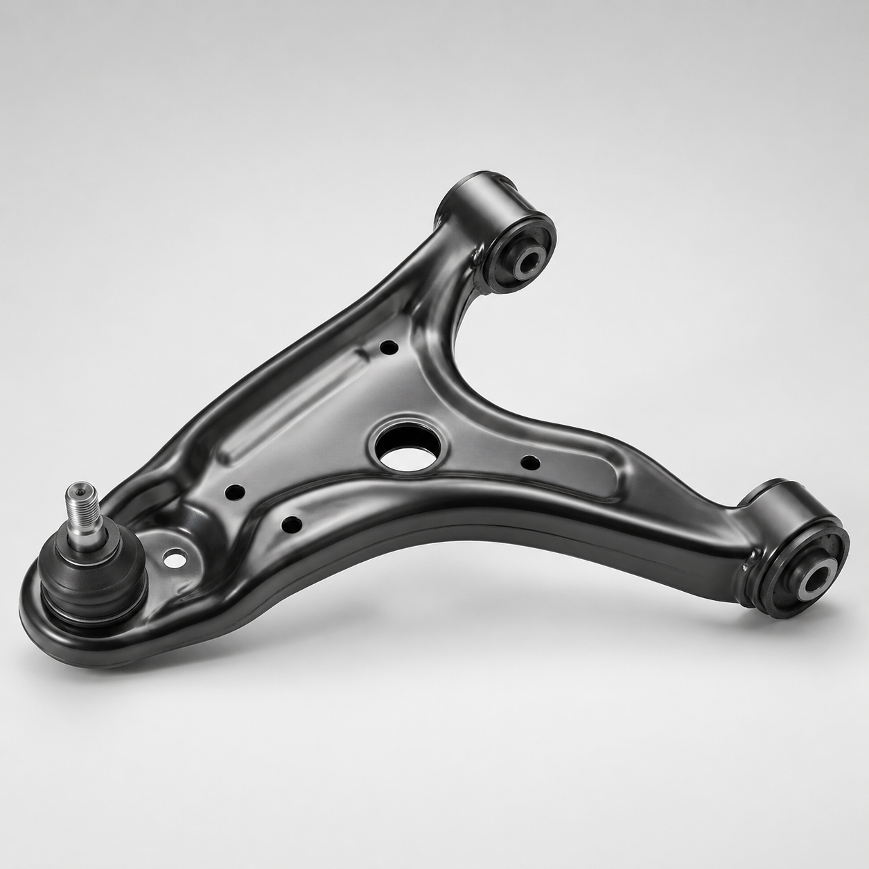
Lift out the assembly and compare it with the replacement on the bench. Check port spacing, flange thickness, bracket location, studs, and any actuator or sensor interfaces. On B2B inspection, record critical dimensions such as centre-to-centre flange spacing, hose neck outside diameter, and bracket offset. A quick caliper check is cheaper than stripping the job twice.
5. Clean mating surfaces properly
Remove gasket residue and carbon without gouging the base metal. Then inspect adjoining pipes and faces for cracks, pitting, or warp. If the mating side is already damaged, a new cooler may still leak. Any groove across the sealing track, corrosion chain, or flange warp beyond vehicle or buyer specification should trigger replacement of the related pipe or manifold connection.
6. Install the new cooler with new seals
Use new gaskets and O-rings. Position the unit squarely, hand-start all fasteners, and tighten in sequence to vehicle specification. Many EGR cooler fasteners land in the 8 to 25 Nm range for smaller bolts and 20 to 35 Nm for larger bracket or pipe fixings, but the vehicle data must control the final setting. Over-tightening distorts flanges. Uneven tightening creates leaks. Replacing questionable studs is usually cheaper than a repeat labour event.
7. Reconnect coolant and ancillaries
Refit hoses, exhaust pipes, brackets, heat shields, sensors, and any removed intake parts. Confirm that nothing is touching hot or vibrating components. Hose clamps should sit correctly behind the bead and apply even compression; slow seepage after the first heat cycle is often just a clamp-position error.
8. Refill and bleed the cooling system
Refill with the correct coolant grade and bleed according to the engine procedure. Air pockets around the cooler can cause local overheating, poor heater output, unstable pressure behaviour, and false leak symptoms. Vacuum filling is preferable on more complex layouts because it reduces trapped air and lowers comeback risk.
9. Run, monitor, and verify
Start the engine, bring it to operating temperature, and inspect for coolant leaks, exhaust leakage, abnormal pressure rise, and fault codes. Clear stored codes only after the repair is confirmed and any required adaptation or drive cycle is complete. A practical routine is 10 to 15 minutes at idle, a controlled warm-up, then a road test with at least one moderate-load event so live EGR command, coolant stability, and pending faults can be reviewed.
For multi-site operations, the post-repair record should include pressure-test result, scan result, road-test confirmation, installed part number, lot code, labour time, and which companion parts were replaced or reused. That record helps with warranty control and pattern tracking.
Failure Modes After Installation: What Usually Gets Missed
A newly fitted cooler does not mean the job is finished. Many returns are not caused by the replacement part. They come from a good install wrapped around an unresolved system fault.
Inspect these points before release:
Cooling system pressure retention: verify no pressure drop during the specified hold period; many workshops use 10 to 15 minutes as a minimum static check
Exhaust joint sealing: check for soot marks, ticking noise, or audible leakage at flanges
EGR command response: confirm expected live data values during idle and loaded conditions
Coolant contamination: inspect for oil, soot, or combustion residue in the expansion tank
Mount stability: confirm brackets are seated correctly and no pipe is under tension
Regeneration and aftertreatment status: review DPF-related data where the engine platform links EGR flow to emissions strategy
Also verify heater performance, monitor coolant level after the initial heat cycle, and confirm that no stored faults return after a short road test. Where the scan tool allows it, compare pre-repair and post-repair values for EGR temperature, differential pressure behaviour where relevant, and any coolant temperature irregularity under load.
A useful rule for workshop managers: if the repair included seals, pipework, or hose disturbance, inspect again after full cool-down. Some leaks appear only after contraction. Where emissions compliance testing forms part of fleet maintenance, post-repair checks should align with the vehicle's applicable regulatory framework. Depending on market and vehicle class, related references may include ECE R-83 for pollutant emissions requirements.
Buyer Comparison: How to Assess EGR Cooler Supply for Repair Networks
For distributors and repair groups, the install procedure is only half of the equation. The other half is whether the supplied cooler arrives clean, dimensionally stable, and consistent from lot to lot.
Questions worth asking a supplier:
What leak-test pressure is used on each cooler?
Are coolant-side and gas-side passages checked for contamination after manufacture?
What flange flatness tolerance is controlled in final inspection?
Is lot traceability available on packaging and carton labels?
Are gaskets included, and are seal materials documented?
Can the supplier support private label or custom manufacturing for your distribution network?
Validation depth matters. Buyers should ask whether testing covers thermal cycling, vibration resistance, corrosion exposure, and burst or fatigue performance where relevant to the application. A credible validation stack often includes coolant-side pressure testing around 2.0 to 3.0 bar, thermal cycling over several hundred cycles, corrosion exposure for coated externals, and dimensional reports on each production lot.
Then compare the commercial side with the same discipline. Low-volume emergency supply may justify a higher unit cost if shipment can happen in 7 to 10 days. Planned warehouse replenishment is usually more efficient at 30 to 45 day lead time with consolidated carton quantities. Ask for price breaks by volume tier, carton pack quantity, pallet density, warranty claim procedure, and whether MOQ changes when custom labels, bilingual instructions, or bundled gasket kits are required.
In many programmes, the real landed cost difference does not come from headline piece price. It comes from scrap rate, fitment time, claims handling, and whether the part prevents a second workshop visit.
At Driventus, buyers can review our catalog for applicable engine and emissions-related components alongside EGR cooler programmes. Matching the cooler with validated companion parts such as gaskets, pipes, clamps, and water pump service items can reduce repeat workshop visits. If you are assessing a new source, ask for validation data, sample inspection reports, packaging specifications, MOQ, and standard production lead time before placing a volume order.
Frequently asked questions
Not in every case, but it should always be inspected. If the valve shows sticking, heavy carbon, actuator faults, or related wear, replacing both components can reduce repeat labour and warranty claims. For fleet buyers, bundling cooler, valve, and seals into one service kit can also reduce downtime where failure patterns are known on a specific engine family.
Cleaning may help only when the issue is soot restriction and the core remains structurally sound. If there is internal coolant leakage, cracking, corrosion, or flange damage, replacement is the correct repair. In B2B service terms, cleaning is usually viable only when pressure retention is confirmed and the labour cost stays below the installed cost of a new validated unit.
Request dimensional inspection data, leak-test records, material declarations where relevant, traceability details, and evidence of manufacturing control to IATF 16949:2016 and ISO 9001:2015. It is also useful to ask for flange flatness criteria, thermal-cycle validation summary, packaging specification, and standard MOQ and lead-time terms for repeat orders.
If you are sourcing EGR coolers for distribution, workshop groups, or OEM service supply, contact Driventus to discuss specifications, validation data, MOQ, lead time, and batch requirements. You can [request a quote](/contact.html).