engine valve · 2026-05-31

Carbon Buildup on Intake Valves: Engine Valve Checks

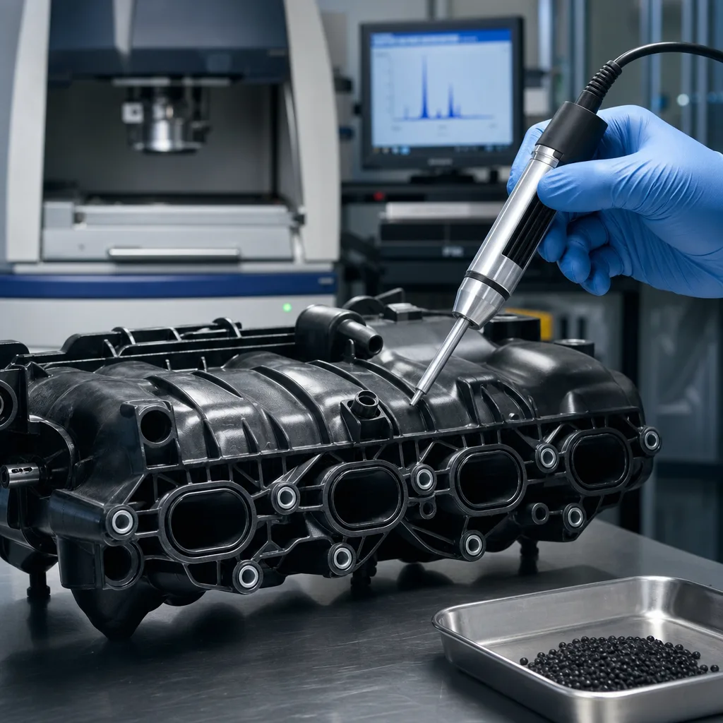
Carbon buildup on intake valves is a common cause of rough idle, cold-start misfire, lower volumetric efficiency, weak throttle response, and repeat drivability complaints in modern petrol engines. It is especially common in gasoline direct injection (GDI) applications, where fuel is sprayed into the chamber instead of washing across the back of the valve. For procurement teams, engine rebuilders, and workshop buyers, the real question is not just how much carbon is visible. The valve head, face, margin, stem, keeper groove, guide interface, and seat contact all have to remain within the engine maker's service limits after heat cycling, oil contamination, and contact with abrasive particles.

Intake deposits can conceal face pitting, margin loss, stem scoring, guide wear, and seat contact defects. They can also disrupt tumble or swirl flow through the port, create cylinder-to-cylinder air imbalance, and cause faults that are not obvious from diagnostic trouble codes alone. In engines exposed to short-trip duty, long oil intervals, high crankcase ventilation load, turbocharger oil carry-over, or heavy EGR flow, deposits often return unless the root cause is corrected.

Driventus is an independent aftermarket manufacturer; brand names are referenced for fitment only. We supply engine valve programmes for distributors, repair chains, wholesalers, and OE-related channels with dimensional control, batch traceability, and compliance support.

Why intake valves collect carbon

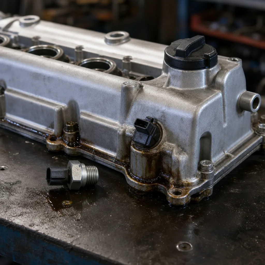
Carbon buildup on intake valves is usually driven by oil vapour, crankcase ventilation, combustion by-products, EGR flow, temperature profile, and duty cycle. Valve material matters, but it is rarely the whole story. In port fuel injection engines, fuel passes across the back of the intake valve and can dissolve light oily residue before it polymerises and hardens. In GDI engines, the injector sprays directly into the combustion chamber, so this fuel-wash effect is largely absent. Oil mist from the PCV system, soot and inert gas from EGR, fine particulate contamination, and moisture from repeated cold starts can then cling to the valve head, neck, tulip area, and upper stem.

The deposit layer often begins as a sticky oil film. As the valve moves between intake-port temperatures and combustion-adjacent heat, lighter fractions evaporate and heavier hydrocarbons oxidise into harder carbonaceous residue. Typical intake valve back-face temperatures vary by engine load and location, but GDI intake valves often run cool enough in part-load service for oil-derived deposits to remain stable instead of burning away. Short-trip engines are especially exposed because coolant, oil, and the intake tract may not stay at full operating temperature long enough to purge moisture and volatile fractions. Turbocharged engines add another pathway when compressor-side oil carry-over, worn turbo seals, or elevated crankcase pressure increase oil mist in the charge-air path.

Typical contributors include:

  • High oil carry-over through the PCV system, blocked oil separators, or excessive crankcase pressure
  • Extended idling, low-load operation, and urban stop-start service with low valve temperature
  • Short-trip driving with repeated cold starts, fuel enrichment, and incomplete warm-up
  • Worn piston rings, cylinder wear, or excessive blow-by increasing oil vapour load
  • Turbocharger compressor oil leakage or charge-air cooler oil pooling
  • EGR loading that adds soot and increases deposit adhesion in the intake stream
  • Injector imbalance, combustion instability, or poor fuel atomisation affecting cylinder deposits and trims
  • Long oil service intervals, high-volatility oil, or incorrect oil specification increasing deposit tendency

Deposits reduce effective port area, disturb air motion, and may stop the valve from closing cleanly against the seat if carbon reaches the seat contact region. The result is not always sudden failure. It may show up as small differences in cylinder filling, unstable idle, elevated fuel trims, or gradual torque loss. During inspection, the visible carbon layer is only one part of the decision. Seat contact width, valve margin, face condition, stem diameter, stem straightness, and stem-to-guide clearance must be checked against the applicable service specification before deciding whether the valve can remain in service.

Symptoms that point to valve deposit problems

An intake-side deposit issue usually appears first as drivability loss, then as measurable performance deviation. Common symptoms include rough idle, hesitation on light throttle, cylinder-specific misfire codes, longer cranking, uneven cold-start quality, and unstable combustion below roughly 1,500 rpm. In fleet operation, fuel consumption often rises before a warning lamp appears because the engine control unit can compensate for moderate airflow and mixture differences until fuel trim, misfire, or load-calculation thresholds are exceeded.

Deposit-related symptoms are often cylinder-specific. One intake port may carry a heavier carbon load because of manifold runner geometry, PCV entry location, EGR distribution, injector condition, local wall temperature, or valve-guide oil leakage. That can leave one weak cylinder even when the overall mass airflow reading looks reasonable. For workshops and warranty teams, scan data should therefore be compared with mechanical tests instead of treated as a complete diagnosis.

Common field indicators

</tr></thead><tbody> </tbody></table>A borescope can show deposit formation and runner-to-runner variation, but it cannot prove that the valve face is still sealing correctly. Heavy carbon may hide pitting, margin loss, tulip deformation, or face recession until the valve is cleaned or removed. For a reliable decision, use compression testing, cylinder leak-down testing, cylinder balance data, and, where the cylinder head is removed, valve runout and guide-clearance measurements. The important distinction is whether the valve is only contaminated or whether sealing geometry and working dimensions have already moved outside the service limit.

Inspection steps before replacing the valve

Before ordering replacement parts, confirm whether the problem is limited to deposits or whether the valve has measurable wear. A structured inspection sequence reduces avoidable returns, helps buyers match the correct part family, and gives service teams a defensible basis for choosing cleaning, machining, or replacement. It also prevents a common repeat-repair problem: replacing visible components while leaving the oil control, PCV, EGR, turbocharger, or valve-guide condition that caused the deposit problem unchanged.

Recommended inspection sequence:

1. Read diagnostic trouble codes, freeze-frame data, short- and long-term fuel trims, misfire counters, load values, and coolant temperature at fault occurrence. 2. Check crankcase ventilation flow, PCV valve operation, oil separator condition, intake oil pooling, and oil consumption history. 3. Inspect the air intake, throttle body, charge-air path, manifold runners, and intake ports with a borescope. 4. Compare deposit severity across cylinders and identify whether the pattern follows PCV, EGR, manifold, or guide-oil distribution. 5. Perform compression and cylinder leak-down tests to identify sealing loss before disassembly. 6. Confirm injector balance, ignition condition, cam timing, and valve timing control before condemning the valve train. 7. Remove the cylinder head if sealing loss is confirmed or if cleaning exposes suspicious face, margin, seat, or guide wear. 8. Measure valve margin, stem diameter at several points, overall length, stem straightness, face runout, and head condition. 9. Check guide clearance, seat width, seat concentricity, seat angle, and contact pattern with marking compound or equivalent equipment. 10. Record measurements against the engine specification before approving reuse, reconditioning, or replacement.

Service limits vary by engine family, but the principle is consistent. If the valve face is pitted, the margin is below specification, the stem is scored or worn beyond tolerance, or the contact pattern is too wide, uneven, or off-centre, cleaning alone is not a durable repair. Excessive guide clearance can also draw oil into the port and speed up new carbon buildup. A valve that no longer seals correctly raises local temperature at the face edge and can progress to leakage, burnt valves, low compression, or repeat misfire complaints.

For procurement, the inspection result should translate directly into part selection. Confirm engine code, application year range, head diameter, stem diameter, overall length, keeper groove design, seat angle, valve head profile, and any required coating or surface treatment before placing an order. For catalogue selection, see our catalog and, where relevant, engine components.

What to verify when sourcing replacement engine valves

For procurement teams, the priorities are OE fitment, metallurgical consistency, dimensional stability, and batch-to-batch repeatability. A replacement intake valve may look simple, but small deviations in stem diameter, head profile, face angle, keeper groove position, or margin thickness can affect guide fit, sealing, installed height, spring geometry, oil control, and heat transfer into the seat. When carbon buildup intake valves engine valve replacement decisions are made across multiple workshops, these details determine whether the repair programme stays consistent by engine code, region, and production batch.

Key points to verify:

  • Overall length and head diameter against the target engine application and OE cross-reference
  • Stem diameter, roundness, surface finish, hard-chrome or nitrided layer where specified, and straightness
  • Valve face angle, seat angle, face finish, and contact geometry after lapping or machining
  • Margin thickness, head thickness, and tulip profile for mechanical strength and thermal durability
  • Keeper groove design, groove location, and compatibility with retainers, collets, and installed spring height
  • Material grade for intake duty, including corrosion resistance, fatigue strength, and hot-strength requirements
  • Surface treatment, nitriding, chrome plating, or other coating where the OE design requires it
  • Packaging protection to prevent stem nicks, head-edge damage, and corrosion during transport
  • OE-number cross-reference, engine-code mapping, application-year coverage, and supersession control
  • Traceability by batch, production date, heat or material lot, and inspection record

Driventus manufactures to controlled specifications and can support validated programmes for aftermarket and OE-related supply. We align production systems with IATF 16949:2016 and ISO 9001:2015 quality controls. For markets with regulatory screening, compliance documentation may also be supported against REACH (EC) No 1907/2006 where applicable to material declarations. If you need dimensional alignment for a specific application, our custom manufacturing service is available for drawing-based programmes.

Symptom Likely effect on the valve train Inspection priority
Rough idlePartial airflow restriction, unstable mixture motion, or poor seatingCarbon load on valve head, neck, and seat contact area
Cold-start misfireUneven cylinder filling and weak first-cycle combustionDeposit thickness by port, compression, and leak-down result
Loss of powerReduced volumetric efficiency at higher air demandAirflow data, manifold inspection, and borescope check
High fuel usePoor combustion stability and increased short- or long-term fuel correctionValve sealing, injector balance, fuel trims, and oxygen sensor data
Longer crankingLow first-cycle compression or mixture instabilityCompression, leak-down, cranking speed, and cold-start enrichment data
Persistent fault codesMisfire, lean condition, load calculation error, or cylinder imbalanceScan data combined with mechanical confirmation

</tr></thead><tbody> </tbody></table>

Cleaning versus replacement: where the line sits

Cleaning can restore airflow when the deposit is light to moderate and the valve surface remains within specification. Walnut-shell blasting, controlled media cleaning, and approved chemical cleaning are common workshop methods, especially on GDI engines where access through the intake port is possible. Media selection and containment matter: abrasive residue left in the port or cylinder can damage rings, cylinder walls, guides, and seats. Cleaning removes carbon from the valve head and port area, but once the surface is visible, it still needs dimensional inspection.

Cleaning is usually reasonable when compression and leak-down results are within the engine maker's limit, the borescope shows no edge damage, oil consumption is controlled, and the service history suggests the deposit is mainly related to duty cycle rather than mechanical wear. The repair should also include checks of the PCV valve, oil separator, EGR operation, turbocharger oil carry-over, charge-air cooler oil pooling, injector balance, and oil specification. Without that supporting work, the same intake valve deposits can return quickly.

Replace rather than clean when:

  • The stem shows measurable wear, scoring, galling, corrosion, or poor surface finish
  • The valve face is pitted, heat-checked, recessed, tuliped, or visibly uneven
  • The margin is below the service limit or would fall below limit after refacing
  • The seat contact pattern is too wide, too narrow, off-centre, broken, or inconsistent around the circumference
  • Compression or leak-down results remain poor after cleaning and seat verification
  • Stem-to-guide clearance is outside specification or oil control is poor
  • The engine has repeated deposit recurrence from PCV, oil-control, guide, or turbocharger faults
  • Prior machining would compromise installed height, seat contact geometry, or thermal margin

For buyers managing multiple locations, a standard replacement policy is easier to control than variable rework decisions. It supports more consistent labour times, clearer warranty handling, simpler parts stocking, and fewer repeat visits. This is especially relevant on high-mileage petrol engines where a damaged valve can continue to cause misfire or compression complaints even after the visible carbon has been removed. The practical line is straightforward: clean deposits when the valve still measures correctly; replace the valve when sealing geometry, stem condition, guide interface, or thermal margin is compromised.

How Driventus supports B2B intake valve supply

Driventus manufactures engine valves for distributors, wholesalers, repair networks, engine rebuilders, and export programmes. Our focus is consistent geometry, batch traceability, and controlled production under audited quality systems. We supply from Taizhou, Zhejiang, and export to 60+ countries, supporting customers that need stable intake valve availability for aftermarket replenishment, regional warehouse stocking, mixed-model repair demand, and application-specific sourcing projects.

Buyer support can include:

  • Drawing review, technical data confirmation, and sample approval for application-specific programmes
  • OE-number cross-reference confirmation where available, for example OE 06A107065
  • Engine code, model range, valve head diameter, stem diameter, length, and groove matching support
  • Packaging labelling to customer specification for warehouse, distributor, and retail channels
  • Material, dimensional, coating, and inspection documentation by batch where required
  • Programme support for regional stocking, mixed orders, replenishment planning, and forecast review
  • Coordination for private-label or customer-specific packaging where applicable

For sourcing teams comparing vendors, the main questions are lead time, dimensional consistency, documentation depth, application coverage, and the supplier's ability to support repeat orders without specification drift. A carbon buildup intake valves engine valve issue may begin as a workshop cleaning problem, but at procurement level it becomes a reliability and availability question. The replacement valve must match the engine code, guide system, seat geometry, and retainer package, then arrive with the documentation needed for quality control. You can review our catalog, check our quality system, or request a quote for a specific application. Driventus is an independent aftermarket manufacturer; brand names are referenced for fitment only.

Frequently asked questions

Yes. Deposits can prevent full seating, create local hot spots, restrict airflow enough to destabilise combustion, or hide face and margin wear until leakage develops. Many repeat failures also involve stem wear, excessive guide clearance, seat damage, PCV faults, oil-control problems, or overheating, so inspection is needed before choosing cleaning or replacement.

No. Cleaning is suitable only when the valve face, margin, stem, guide clearance, and seat contact remain within the engine maker's specification. If there is pitting, heat damage, excessive stem wear, poor contact pattern, or weak leak-down results after cleaning, replacement is the correct repair.

Buyers commonly request evidence of ISO 9001:2015 and IATF 16949:2016 quality-system alignment or certification, plus batch-level dimensional inspection records where required. Depending on the market, customer requirements, and material set, REACH documentation and material declarations may also be needed.

If you are comparing intake valve supply options or need a fitment check for a specific engine family, please [request a quote](/contact.html).

Request a Quote
Verification item Why it matters Buyer risk if missed
Stem diameterControls guide fit, oil control, valve motion, and stem-to-guide clearanceOil consumption, noise, sticking, or accelerated guide wear
Stem surface finishAffects guide wear, oil-film control, and scuffing resistancePremature guide wear, seizure risk, or repeat oil-fed deposits
Seat angleDetermines contact pattern, sealing, and heat transfer into the seatLeakage, poor compression, and burnt valve risk
Head thicknessSupports strength under cyclic loading and thermal exposurePremature cracking, deformation, or fatigue failure
Margin thicknessProtects the valve edge after seating, lapping, and service wearEdge overheating, recession, or early leakage
Keeper groove positionMaintains installed height, spring preload, and retainer clearanceIncorrect assembly, spring load variation, or retainer interference
Material controlEnsures durability under intake temperature, corrosion, and fatigue exposureUneven service life across batches and inconsistent warranty outcomes
Batch traceabilitySupports containment, replacement campaigns, and root-cause analysisHarder recall management and weaker supplier accountability