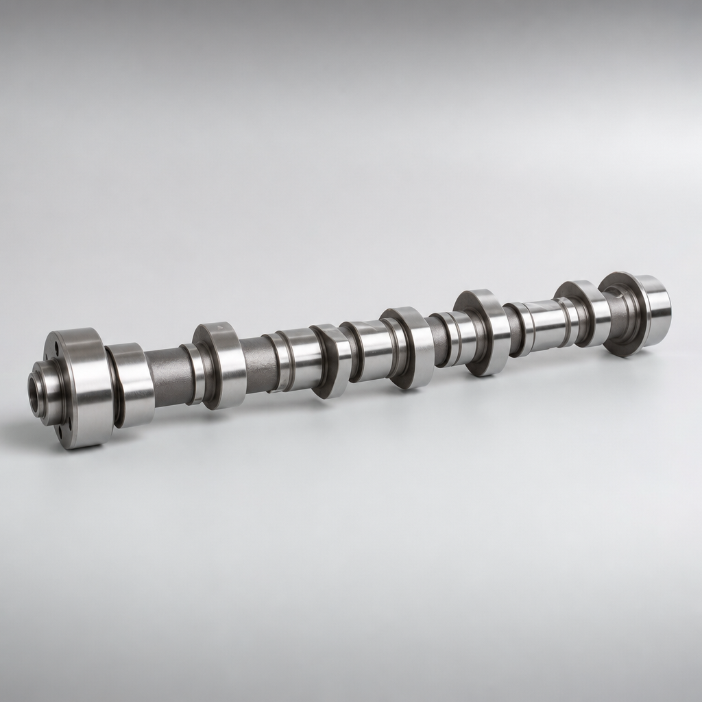
Camshaft Mitsubishi OEM Supplier Sourcing Guide
Sourcing a Mitsubishi-fitment camshaft involves more than price comparison. For distributors, Tier-1 programmes and repair-chain buyers, the sourcing decision affects valve-train durability, warranty exposure, inventory accuracy and import compliance. A qualified camshaft Mitsubishi OEM supplier should be able to document metallurgy, lobe geometry, surface treatment, dimensional controls and batch traceability before purchase orders are released. Driventus Auto Parts manufactures engine and powertrain components in Taizhou, Zhejiang, and exports to more than 60 countries. Our camshaft supply is structured for B2B procurement: cross-reference management, PPAP-style documentation when required, incoming material inspection, CNC grinding controls, hardness verification and packing suitable for sea or air freight. Driventus is an independent aftermarket manufacturer; brand names are referenced for fitment only. This guide explains what buyers should verify when sourcing camshafts for Mitsubishi applications, including audit questions, typical MOQ and lead-time factors.
Buyer Requirements for Mitsubishi-Fitment Camshaft Supply
Procurement teams usually start with a part number list, but a technical quotation should define more than interchangeability. Camshafts control valve timing, lift and duration, so minor deviations in lobe profile or journal geometry can cause noise, power loss, accelerated follower wear or oil-pressure issues.
For Mitsubishi applications, buyers may request camshafts for petrol and diesel engines across passenger cars, light commercial vehicles and regional aftermarket fleets. Driventus supports enquiries by OE-style references when available, engine code, application table, sample drawing or original sample. If the buyer provides an OE cross-reference such as OE 06A107065 only as a format example, it should not be treated as Mitsubishi fitment without technical confirmation.
A practical sourcing file should include:
- Engine code, model year range and market region
- Intake or exhaust camshaft position where applicable
- Material requirement: chilled cast iron (typical hardness 45–55 HRC), ductile iron (e.g., GJS-700) or forged steel (e.g., 42CrMo4, 55 HRC min.), depending on design
- Surface treatment and hardness requirement: induction-hardened lobe flanks to 50–58 HRC, nitrided to 0.2–0.5 mm case depth, or chilled cast iron as-cast
- Journal diameter tolerance: ±0.025 mm typical; lobe lift tolerance: ±0.05 mm typical
- Packaging specification and label format: individual polybag with part number, lot code, and barcode; export carton with HS code and country of origin
- Annual demand, first order quantity and forecast horizon: e.g., 2,000 pcs/year, first order 500 pcs, 12-month rolling forecast
- Required documents: inspection report (dimensional, hardness, runout), material certificate (EN 10204 3.1), capability study (Cp/Cpk ≥ 1.33 for critical dimensions), or PPAP Level 3 package
Buyers can review related engine parts in our catalog and the engine component range at /products/engine-components.html when consolidating camshafts with pistons, crankshafts, gaskets or water pumps.
Manufacturing Route and Critical Control Points
Camshaft production is process-sensitive. A visually acceptable part can still fail if the core metallurgy, lobe hardening depth or grinding profile is unstable. Driventus controls camshaft production through defined routing, in-process measurement and final inspection records.
Typical process flow:
1. Raw material verification and casting or forging inspection: spectrometric analysis (e.g., C 3.2–3.6%, Si 1.8–2.4% for chilled cast iron) and ultrasonic testing for internal defects 2. Straightening and rough machining of journals and reference features: runout held to ≤0.1 mm before heat treatment 3. Heat treatment or surface hardening according to product design: induction hardening at 200–300 kHz, tempering at 180–220°C for 2 hours; case depth 1.5–3.0 mm for lobes 4. CNC grinding of journals, lobes and thrust faces: finish grinding with CBN wheels, surface roughness Ra ≤ 0.4 µm, roundness ≤ 0.005 mm 5. Deburring, cleaning and anti-corrosion protection: aqueous wash with rust inhibitor, oil-hole blow-out with 0.5 MPa compressed air 6. Hardness, runout and dimensional inspection: 100% check on lobe lift, journal diameter, runout (≤0.03 mm total), and hardness (Rockwell C scale) 7. Packing with part identification and batch traceability: laser-etched lot code on non-functional face, individual polybag with desiccant
Key control points include journal roundness (≤0.005 mm), cam lobe lift (±0.05 mm), base circle diameter (±0.025 mm), keyway or trigger feature position (±0.1 mm), straightness (≤0.02 mm over 300 mm), and surface roughness (Ra ≤ 0.4 µm). For overhead camshaft designs, oil-hole cleanliness is also critical because restricted lubrication can damage cam journals and followers quickly after installation.
Driventus does not claim approval or endorsement by any vehicle manufacturer. Parts are produced for independent aftermarket and contractual supply programmes, using buyer-approved specifications, validated drawings or confirmed samples.
Specifications Buyers Should Request Before Award
A camshaft Mitsubishi OEM supplier should respond with measurable specifications, not only application claims. The exact values depend on the engine family and drawing, but the quotation stage should confirm which parameters are controlled and how they are measured.
| Specification item | Why it matters | Typical verification method | Example tolerance | ||
|---|---|---|---|---|---|
| Material grade | Affects strength, wear resistance and machinability | Spectrometer analysis, material certificate | Chilled cast iron: C 3.2–3.6%, Si 1.8–2.4%; 42CrMo4: C 0.38–0.45%, Cr 0.9–1.2% | ||
| Lobe lift and profile | Controls valve event and engine performance | Cam profile measuring instrument, CMM where required | Lobe lift ±0.05 mm; profile deviation ≤0.02 mm | ||
| Journal diameter | Affects oil clearance and bearing support | Micrometer, air gauge, CMM | ±0.025 mm; typical 50.000–50.025 mm | ||
| Runout / straightness | Reduces valve-train noise and bearing load | Dial indicator, V-block inspection | Total runout ≤0.03 mm; straightness ≤0.02 mm/300 mm | ||
| Surface hardness | Controls wear at lobe and journal contact surfaces | Rockwell or Vickers hardness testing | Lobe flanks 50–58 HRC; journals 45–55 HRC | ||
| Surface roughness | Supports oil film retention and follower durability | Roughness tester | Ra ≤ 0.4 µm on lobes; Ra ≤ 0.6 µm on journals | ||
| Oil-hole cleanliness | Prevents lubrication restriction | Visual inspection, air flushing, cleanliness check | No debris >0.5 mm; particle count per ISO 16232 | ||
| Batch traceability | Supports containment and warranty investigation | Lot code, production record, inspection report | Unique lot code per heat-treatment batch; records retained 10 years |
| Scenario | Tooling status | Indicative MOQ driver | Lead-time driver | Example MOQ | Example lead time |
|---|---|---|---|---|---|
| Existing aftermarket reference | Existing tooling | Carton quantity or batch efficiency | Finished stock, grinding capacity, export booking | 50–200 pcs per SKU | 15–30 days from stock; 45–60 days for production |
| Low-volume regional application | Existing rough blank, new finish setup | Minimum heat-treatment or grinding lot | Fixture setup, inspection plan approval | 100–500 pcs | 60–90 days |
| New development from sample | New or modified tooling | Casting/forging batch and validation cost | Reverse engineering, trial production, validation | 500–2,000 pcs | 90–150 days |
| Contract supply programme | Buyer-approved drawing | Annual forecast and safety stock plan | PPAP timing, audit, capacity reservation | 2,000–10,000 pcs/year | 60–90 days after PPAP approval |