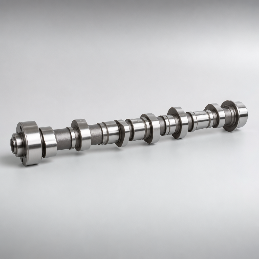
Camshaft for Lexus IS Replacement: Buyer Checklist
A camshaft for Lexus IS replacement is a precision timing component, not a simple catalogue item. For distributors, repair-chain buyers, and engine rebuilders, the sourcing decision affects valve timing accuracy, warranty exposure, installer confidence, and repeat fitment across Lexus IS engine variants such as 2.5L, 3.0L, 3.5L petrol and hybrid-market applications. Replacement camshafts should be selected by engine code, cam position, bank, valve-train layout, VVT/VVT-i interface, journal dimensions, sensor features, and buyer-approved part-number cross-reference. This guide sets out procurement checks that matter for OE-equivalent aftermarket supply: measurable dimensions, realistic tolerances, material and heat treatment controls, inspection sampling, validation testing, MOQ and lead-time logic, traceability, packaging, and import documentation. Driventus manufactures engine and powertrain components in Taizhou, Zhejiang, with controls aligned to IATF 16949:2016 and ISO 9001:2015. Driventus is an independent aftermarket manufacturer; vehicle brand names are used only to identify fitment.
Decision Framework: Matching the Right Camshaft to the Engine, Not the Badge
“Lexus IS” is a starting point—not a purchase order. Intake and exhaust camshafts diverge by engine code, cylinder bank, valve-train architecture, VVT system, model-year update, and regional emissions package. A wrong bank or trigger feature can install physically but still create timing correlation faults, unstable idle, or phaser control errors.
For a camshaft for Lexus IS replacement RFQ, require the supplier to confirm at least the following before quotation:
- Vehicle application: Lexus IS model, destination market, model year range, engine code, and displacement
- Camshaft position: intake or exhaust, plus left bank/right bank or bank 1/bank 2 where applicable
- Valve-train type: direct-acting bucket, roller follower, finger follower, or rocker arrangement
- Variable valve timing interface: phaser mounting face, oil feed location, dowel diameter and clocking, bolt pattern, centre bore, oil-control groove, and sealing land
- Sensor features: trigger wheel, reluctor profile, tooth count, slot width, missing-tooth position, or cam position reference feature if integrated
- Critical dimensions: journal diameters, journal count and spacing, lobe layout, overall length, thrust face, end feature design, thread size, and keyway or pin location
- OE or aftermarket cross-reference: only where supplied and approved by the buyer for identification, not as proof of brand endorsement
- Quantity, packing standard, documentation level, warranty administration requirements, and target release date
Useful RFQ evidence includes 6-side photos, caliper readings for overall length and journal diameters, close-up photos of the phaser end and sensor end, and a sample tag showing the buyer’s current part number. Where no drawing exists, send one unused master sample and one failed field sample if available; the failed sample helps distinguish original design features from wear damage.
A reliable camshaft programme should support cross-reference verification without implying approval by the vehicle manufacturer. Driventus is an independent aftermarket manufacturer; brand names are referenced for fitment only. Buyers consolidating engine sourcing can also review adjacent product families in our catalog and the engine components range.
Spec Deep-Dive: The Numbers That Separate a Camshaft from a Claim
OE-equivalence lives in measurable characteristics, not visual similarity. The component has to preserve valve opening events, stable oil film on bearing journals, phaser alignment, sensor signal behaviour, and long-term wear resistance under mixed lubrication.
Buyer-level specifications should be agreed from the drawing, master sample, or validated reverse-engineering file. The numbers below are practical aftermarket control targets often used as quotation baselines; final limits must follow the specific engine design.
| Criterion | Procurement requirement | Typical control target | Why it matters |
|---|---|---|---|
| Overall length and end features | Matched to drawing, approved sample, or validated specification | ±0.10–0.20 mm unless otherwise defined | Controls axial location, installation fit, and mating clearance |
| Journal diameter and roundness | Controlled within the specified tolerance band | Diameter commonly ±0.010–0.020 mm; roundness ≤0.005–0.010 mm | Affects oil clearance, noise, oil pressure, and seizure risk |
| Journal width and spacing | Verified against datum structure | ±0.03–0.05 mm on critical locations | Prevents bearing edge loading and axial misalignment |
| Cam lobe lift and base circle | Verified per lobe against the profile specification | Lift ±0.02–0.05 mm; base circle ±0.02 mm where required | Maintains airflow, combustion balance, and valve-train geometry |
| Lobe phase angle | Checked against a defined datum | Often ±0.25°–0.50° cam angle on critical lobes | Prevents timing deviation, drivability issues, and diagnostic codes |
| Runout | Inspected between centres or on approved fixtures | ≤0.03–0.05 mm TIR depending on length | Reduces vibration, uneven journal loading, and abnormal wear |
| Surface hardness and case depth | Confirmed after heat treatment | Lobe surface commonly 50–60 HRC or equivalent; case depth defined by material/process | Supports wear resistance on lobes, journals, and contact areas |
| Surface roughness | Measured on journals, lobes, and thrust faces | Journals often Ra 0.2–0.4 µm; lobes Ra 0.3–0.8 µm | Influences lubrication film formation and bedding behaviour |
| Oil holes and galleries | Deburred, cleaned, and flow-checked where applicable | No visible burrs; oil path verified by air or fluid check | Helps prevent phaser malfunction or journal oil starvation |
| Phaser and sensor interface | Gauged or dimensionally verified | Bolt circle, centre bore, dowel, trigger features checked 100% when high risk | Protects timing control accuracy and ECU position recognition |
| Test or validation item | Typical purpose | Buyer evidence to request |
|---|---|---|
| Material verification | Confirms grade and chemical composition | Mill certificate, spectrometer result, or laboratory report |
| Hardness and case-depth study | Confirms wear surface specification | Heat treatment report and section analysis where required |
| Cam profile measurement | Confirms lift curve, base circle, opening/closing ramp, and phase | Profile report referenced to the defined datum |
| Endurance bench test | Assesses lobe wear, journal durability, and phaser interface performance | Test summary, duration, load condition, lubricant, temperature, and acceptance criteria |
| Metallographic analysis | Checks microstructure, chill depth, hardening quality, decarburisation, and defects | Laboratory section report with photos where specified |
| Corrosion or packing-route test | Assesses storage and ocean freight risk | Salt spray, humidity, or packing validation report when specified |
| Installation trial on reference cylinder head | Confirms assembly fit, free rotation, axial float, and mating interface | Fitment record with sample identification and torque conditions |
| Cleaning verification | Confirms oil passages are free of harmful contamination | Cleanliness report, residue mass limit, or process record |