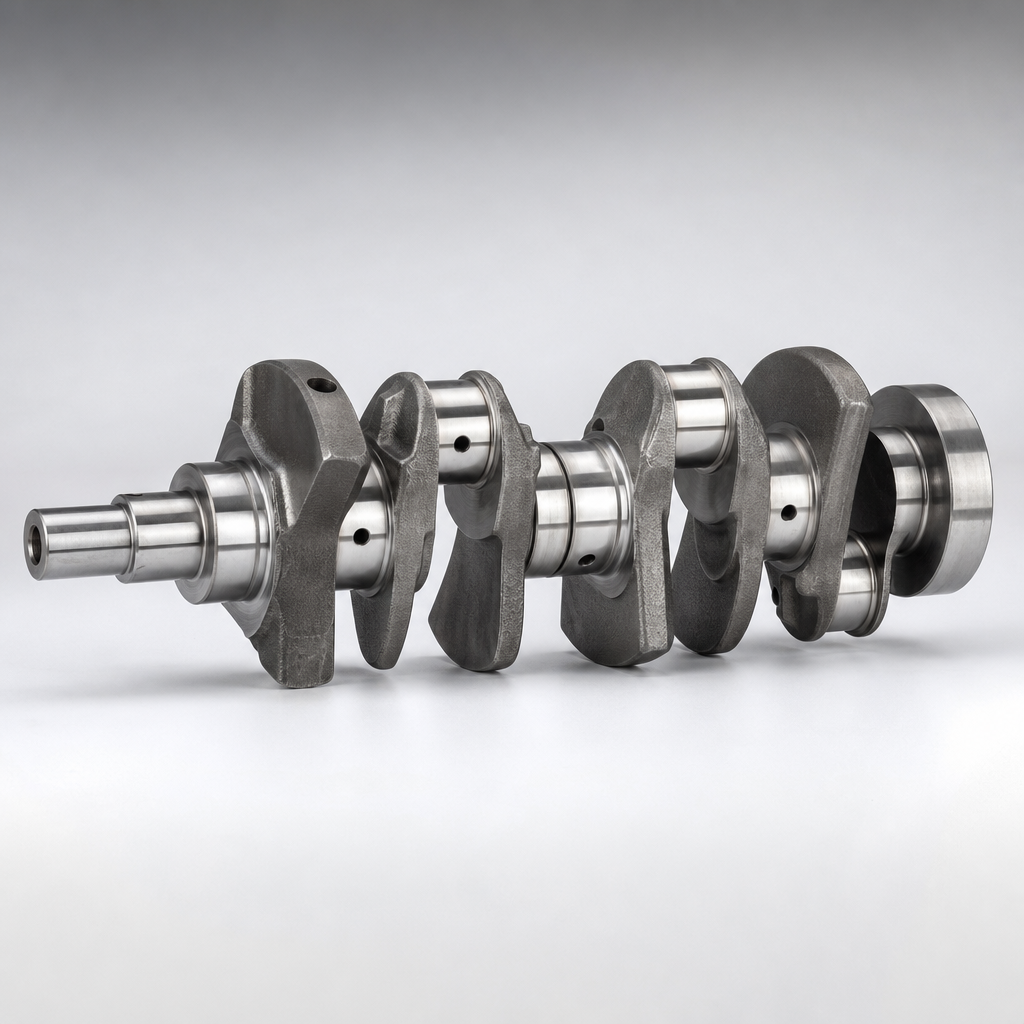
Camshaft for Kia Optima Replacement: OE Match Checks
A camshaft replacement for a Kia Optima demands more than a visual match. Buyers must confirm engine code, journal diameter, lobe profile, overall length, trigger arrangement, and surface finish before placing an order. A part that fits the head but fails to match valve timing, sensor indexing, or hardness can lead to repeat returns and downstream warranty claims.
Driventus supplies camshafts for B2B replacement programs with dimensional control, heat-treatment traceability, and inspection records aligned to IATF 16949:2016 and ISO 9001:2015. Driventus is an independent aftermarket manufacturer; brand names are referenced for fitment only. For procurement teams, the practical question is whether the replacement camshaft matches the OE envelope closely enough to preserve assembly fit, lubrication behavior, and timing stability. This article outlines the checks that matter before sourcing, receiving, or validating a camshaft for Kia Optima applications.
The Fitment Decision Framework: Beyond the Model Name
Stop searching by model year. Kia Optima engine bays from 2011–2020 hold a mix of G4KE, G4KJ, G4NA, and G4FJ families. A single listing that says “fits Optima” is a red flag. Start with the engine code stamped on the block, then lock down the position—intake or exhaust—and the valve count. A 16V G4KE intake shaft is not interchangeable with a 24V G4NA exhaust shaft, even if both bolt in.
Critical match points and their typical tolerances:
- Overall length: ±0.25 mm; bearing journal spacing: ±0.05 mm
- Journal diameter: ±0.013 mm (typical Clevite or OE spec)
- Concentricity (runout): ≤0.025 mm on journals, ≤0.05 mm on lobes
- Lobe lift: ±0.05 mm; base circle: ±0.025 mm; lobe separation angle: ±0.5°
- Trigger wheel or reluctor pattern: 4- or 6-tooth, orientation ±0.5°
- Thrust face geometry: width ±0.1 mm, perpendicularity ≤0.05 mm
- Surface hardening depth: 1.5–3.0 mm (chilled cast iron) or 0.5–1.5 mm (case-hardened steel)
- Surface finish: Ra ≤0.4 µm on journals, Ra ≤0.8 µm on lobes
- Oil feed hole location: ±0.1 mm, diameter ±0.05 mm, where applicable
If any of these drift, the camshaft installs but runs outside the intended valve timing window. That’s a sourcing failure, not a field adjustment.
The Most Common Failure Modes That Trigger Returns
Returns spike when a part looks right but isn’t. Distributors see the same patterns repeat. Knowing them lets you build a receiving inspection that catches problems before installation.
- Wrong engine code cross-reference (20% of returns). The listing matched the model but not the specific engine variant.
- Incorrect intake/exhaust assignment (15% of returns). The shaft fits the journal saddles but the lobe orientation is reversed.
- Trigger wheel orientation error (12% of returns). A 5° offset on the reluctor ring causes a cam/crank correlation fault.
- Packaging damage to precision surfaces (10% of returns). Scratches deeper than 0.1 mm on a journal from loose packing.
- Lobe profile mismatch (10% of returns). Lift or duration is off, altering valve overlap and idle quality.
- Journal diameter outside tolerance (8% of returns). An extra 0.02 mm causes tight clearance and scuffing.
- Improper hardening (5% of returns). Hardness below 50 HRC leads to rapid lobe wear.
Separate shipping damage from engineering mismatch in your claims process. A disciplined triage makes supplier corrective action faster and prevents repeat failures.
Chilled Cast Iron vs. Case-Hardened Steel: A Spec Comparison
Camshaft durability hinges on the core material and surface treatment. Most aftermarket programs use chilled cast iron (G3500 grade, 45–55 HRC) or forged steel (4140/4340, case-hardened to 58–62 HRC). The right choice depends on engine loading, valvetrain geometry, and what the OE used.
| Control item | Chilled cast iron | Case-hardened steel | Why it matters |
|---|---|---|---|
| Typical hardness | 45–55 HRC | 58–62 HRC surface | Determines lobe and journal wear resistance |
| Case depth | 1.5–3.0 mm (chilled zone) | 0.5–1.5 mm (carburized/induction) | Supports wear life under boundary lubrication |
| Core toughness | Lower; brittle under impact | Higher; forged grain flow | Affects fracture resistance in high-RPM applications |
| Machinability | Good; consistent chip formation | Requires post-hardening grinding | Influences surface finish and cost |
| Typical application | Naturally aspirated, moderate load | Turbocharged, high-load, or high-RPM | Matches OE design intent |